background image


BDA UP 14 Z – 03/15 – REV. 0 


Page 27 / 71 


Table of Contents 


1


Introduction ............................................................................................................................................. 28


1.1


Product Specification ...................................................................................................................... 28


1.2


Conformity ...................................................................................................................................... 28


1.3


Dealing with the Operating Instruction ........................................................................................... 28


2


Safety ..................................................................................................................................................... 29


2.1


Warning & Safety Precautions in this Operating Instruction .......................................................... 29


2.2


Safety Precautions ......................................................................................................................... 29


2.3


Responsibilities ............................................................................................................................... 31


2.4


Designed Use ................................................................................................................................. 31


2.5


Predictable Misuse ......................................................................................................................... 31


2.6


Hazardous Areas ............................................................................................................................ 32


3


Shipment ................................................................................................................................................ 32


3.1


Packing ........................................................................................................................................... 32


3.2


Packing Contents............................................................................................................................ 32


4


Technical Description ............................................................................................................................. 33


4.1


Operators Guide ............................................................................................................................. 33


4.2


Machine Identification ..................................................................................................................... 34


4.3


Technical Data ................................................................................................................................ 34


4.4


Safety Guard ................................................................................................................................... 34


4.5


Release Button ............................................................................................................................... 35


5


Transport and Installation ....................................................................................................................... 35


5.1


Transport ........................................................................................................................................ 35


5.2


Installation ....................................................................................................................................... 35


6


Commissioning / Connecting to Compressed Air Supply ...................................................................... 36


7


Tooling .................................................................................................................................................... 38


8


Normal Operation / Production Cycle ..................................................................................................... 40


9


Maintenance ........................................................................................................................................... 41


9.1


Maintenance Plan ........................................................................................................................... 41


9.1.1


Daily ......................................................................................................................................... 42


9.1.2


Monthly .................................................................................................................................... 42


10


Problem Handling and Fault Diagnostics ............................................................................................... 42


11


Removal from Service, Demounting, Disassembly, ............................................................................... 43


12


Storage ................................................................................................................................................... 43


13


Disposal .................................................................................................................................................. 43


14


Exploded View Drawing, Spare Part List ............................................................................................... 44


14.1


Exploded View Drawing .............................................................................................................. 44


14.2


Parts List Exploded View Drawing .............................................................................................. 45


14.3


Pneumatic Diagram .................................................................................................................... 47


14.4


Parts List Pneumatic ................................................................................................................... 48


14.5


Accessories overview for re-orders............................................................................................. 48


Summary of Contents for UP 14 Z

Page 1: ...Pneumatische Crimpmaschine Pneumatic Crimp Machine Machine Pneumatique Version UP 14 Z 03 15 REV 0 a WEZAG Company UP 14 Z Betriebsanleitung Operating Instructions Mode d Emploi...

Page 2: ...enstra e 6 CH 8808 Pf ffikon SZ Schweiz Telefon 41 0 55 417 00 30 Ausgabedatum Version 01 03 2015 REV 0 by WDT ToolTech AG Der Nachdruck dieser Anleitung auch auszugsweise gleichg ltig in welcher Form...

Page 3: ...BDA UP 14 Z 03 15 REV 0 Page 3 71 Deutsche Version Inhaltsverzeichnis 4 English Version Table of Contents 27 Version Fran aise Table des mati res 49...

Page 4: ...aschinenidentifikation 11 4 3 Technische Daten 11 4 4 Schutzabdeckung 11 4 5 R ckstelltaster 12 5 Transport und Aufstellung 12 5 1 Transport 12 5 2 Aufstellung 12 6 Inbetriebnahme Anschlie en an das D...

Page 5: ...1 2 Konformit t Die Maschine ist ausschlie lich f r den in der Betriebsanleitung beschriebenen Zweck zu verwenden F r Sch den die aus nicht bestimmungsgem er Verwendung entstehen haftet der Herstelle...

Page 6: ...ber das gesetzliche Mindestalter zu beachten Es ist strikt untersagt j ngeren Personen Zutritt zu der pneumatischen Crimpmaschine UP 14 Z zu gew hren Betreiben Sie die pneumatische Crimpmaschine UP 14...

Page 7: ...llgemein Vorsicht geboten Die Maschine darf ausschlie lich mit montiertem Gesenkpaar und der vorgesehenen Sicherheitsabdeckung betrieben werden Die gro e Aussparung der Schutzabdeckung darf nur mit mo...

Page 8: ...hrleisten dass die Einweisung und Instruktion der Maschine verstanden worden ist muss die Schulung in der Sprache des Bedienpersonals erfolgen Notwendige Qualifikation der Personen die mit dem Einsat...

Page 9: ...hren Sie die Original Verpackung f r einen sp teren Versand und f r die Lagerung der Maschine auf Abmessung Karton 1 Maschine und Blackbox L nge 380 mm Breite 340 mm H he 390 mm Gesamtgewicht 15 5 kg...

Page 10: ...zeichnung 01 Pneumatische Crimpmaschine UP 14 Z 02 Fingerschutz 03 Positioniereraufnahme 04 R ckstell Taster 05 P Druckluft 06 A Steuerdruck 07 P2 Druckluft Fu schalter 08 Typenschild mit Seriennummer...

Page 11: ...bei 6 bar max 14 kN L rmpegel 73 dB A 4 4 Schutzabdeckung Die Crimpmaschine verf gt ber eine spezielle Schutzabdeckung im Lieferum fang enthalten Je nach Verwendung des Gesenkpaars mit Positionierer...

Page 12: ...Fl che auf und sorgen Sie f r Standfestigkeit der Crimpmaschine Stellen Sie sicher dass die Fl che stark genug ist um das Gewicht der Maschine bei normaler Benutzung aufnehmen zu k nnen Sorgen Sie f r...

Page 13: ...ung getrennt wurde Unterbrechen Sie die pneumatische Versorgung bevor Sie die Schutzabdeckung und das Gesenkpaar auswechseln WARNUNG Die pneumatische Crimpmaschine UP 14 Z darf nur in technisch einwan...

Page 14: ...lauch 6 4 mm Druckluftschlauch P der Blackbox mit Anschluss P an der Maschine verbinden PU Druckluftschlauch 6 4 mm Die pneumatische Crimpmaschine UP 14 Z nur mit aufbereiteter ge lter und gereinigter...

Page 15: ...ie beim Arbeiten mit der pneumatischen Crimpmaschine UP 14 Z keine lose Kleidung losen Schmuck oder lange offene Haare welche sich in den Teilen der pneumatischen Crimpmaschine UP 14 Z verfangen k nne...

Page 16: ...ahme 2 montieren und Schraube festziehen 3 Positionierer auf Positioniereraufnahme 2 stecken WARNUNG Die gro e Aussparung der Schutzabdeckung darf nur mit montierter Positioniereraufnahme und aufgeste...

Page 17: ...ilen der Maschine muss frei gehalten werden Es gilt insbesondere f r das Fu pedal Es darf nur mit dem angegebenen Betriebsdruck gearbeitet werden VORSICHT Stellen Sie die Crimpmaschine auf einer ebene...

Page 18: ...d rfen nur von berechtigten und f r diese T tigkeit ausgebildeten Personen ausgef hrt werden Insbesondere Geh use und Abdeckungen d rfen nur von fachkundigem Personal entfernt werden Tragen Sie beim A...

Page 19: ...verfangen k nnen Arbeiten Sie sorgf ltig Geeignete Schutzhandschuhe und Schutzbrille bei Schmierungsarbeiten tragen Beachten Sie die Sicherheitshinweise im Sicherheitsdatenblatt des Schmierfettes bzw...

Page 20: ...n Personen ausgef hrt werden Insbesondere Geh use und Abdeckungen d rfen nur von fachkundigem Personal entfernt werden Tragen Sie beim Arbeiten mit der pneumatischen Crimpmaschine UP 14 Z keine lose K...

Page 21: ...ngsarbeiten d rfen nur von berechtigten und f r diese T tigkeit ausgebildeten Personen ausgef hrt werden Insbesondere Geh use und Abdeckungen d rfen nur von fachkundigem Personal entfernt werden Trage...

Page 22: ...BDA UP 14 Z 03 15 REV 0 Page 22 71 14 Ersatzteilliste 14 1 Explosionszeichnung Abb 14 1...

Page 23: ...linderbuchse 16 12 x12 15 1 2480 89024 Gelenkwelle 1296 18 16 2 8480 99161 Sicherungsring DIN 471 12x1 17 2 8480 84001 O Ring 100x2 DIN 3771 18 1 2480 82016 Zylinderrohr 19 1 2480 84012 Kolben 20 1 24...

Page 24: ...en 47 1 5481 14003 X Aufkleber Release 48 1 5481 03003 X Aufkleber A 49 1 5481 02006 X Aufkleber P 50 1 5481 03005 X Aufkleber P2 51 1 5481 14002 Aufkleber Serien Nr 52 2 5480 81027 X Aufkleber WDT ro...

Page 25: ...BDA UP 14 Z 03 15 REV 0 Page 25 71 14 3 Pneumatik Schema Abb 14 2...

Page 26: ...88079 X L Einschraub Steckverbinder G1 8 6mm 12 1 8480 88100 X Winkel Au en Innen 1 8 13 1 8480 88073 X Abluftdrossel Schalld mpfer 1 8 14 1 8480 88063 X Druckluft Schalld mpfer G1 8 15 1 8480 88071...

Page 27: ...ne Identification 34 4 3 Technical Data 34 4 4 Safety Guard 34 4 5 Release Button 35 5 Transport and Installation 35 5 1 Transport 35 5 2 Installation 35 6 Commissioning Connecting to Compressed Air S...

Page 28: ...for the purpose specified in the operating instruction The manufacturers and suppliers will not be liable for any damages which may result due to the machine being used for a purpose other than that...

Page 29: ...l reglementations according to the minimum age of the personnel operating the pneumatic Crimp Machine UP 14 Z Allowing younger persons access to the machine is strictly prohibited Do not operate the p...

Page 30: ...uard The larger opening of the safety guard is only allowed to be used with mounted locator holding fixture and mounted locator The pneumatic Crimp Machine UP 14 Z may only be set up and operated in p...

Page 31: ...of the various components of the machine Proper operation of the machine To assure full familiarization with the system the training must be conducted in the native language of the operators involved...

Page 32: ...declaration of conformity and operating instructions We recommend that you retain the packing for further dispatch and for storage Dimension Carton 1 Machine and black box Length 380 mm Width 340 mm...

Page 33: ...eumatic Crimp Machine UP 14 Z 02 Safety guard 03 Locator holding fixture 04 Release Button 05 P compressed air 06 A control pressure 07 P2 compressed air foot pedal 08 Label with serial number 09 Blac...

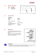
Page 34: ...x 14 kN Noise level 73 dB A 4 4 Safety Guard The pneumatic Crimp Machine UP 14 Z has a special safety guard in the scope of the delivery Based on which die set is used the safety guard has to be mount...

Page 35: ...ion the pneumatic Crimp Machine UP 14 Z on a flat surface and assure the stability of the machine Ensure that the table or bench is stable enough to support the machine in normal use Assure an appropr...

Page 36: ...ected from the air supply Disconnect the air supply before changing the safety guard and the dies CAUTION The pneumatic Crimp Machine UP 14 Z may only be set up and operated in perfect technical condi...

Page 37: ...6 4 mm Connect air hose P of the black box with connection P on the machine PU air hose 6 4 mm Use the pneumatic Crimp Machine UP 14 Z only with conditioned air lubricated and filtered Standard Filte...

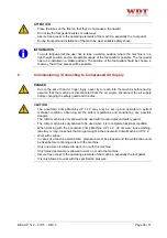
Page 38: ...h the pneumatic Crimp Machine UP 14 Z do not wear loose clothing jewellery or long loose hair that can get caught in the pneumatic Crimp Machine UP 14 Z Work with caution Only one person is allowed to...

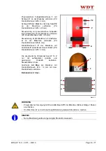
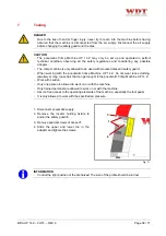
Page 39: ...he locator holding fixture 2 and tighten the screw 3 Put the locator on the locator holding fixture 2 CAUTION The larger opening of the safety guard is only allowed to be used with mounted locator hol...

Page 40: ...s to the operating elements of the machine especially the foot pedal It is only allowed to work with the specified working ATTENTION Position the pneumatic Crimp Machine UP 14 Z on a flat surface and...

Page 41: ...t is only allowed to work with the specified air pressure 9 1 Maintenance Plan DANGER Due to the risk of hand or finger injury never try to reach into the machine before having assured that the machin...

Page 42: ...ng the safety guard and the dies CAUTION Before starting maintenance disassembly or repair work the crimping machine must be disconnected from air supply Maintenance work may be performed only by auth...

Page 43: ...erformed only by authorized and properly trained staff The housing and the covers in particular may only be removed by specially trained staff When working with the pneumatic Crimp Machine UP 14 Z do...

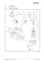
Page 44: ...BDA UP 14 Z 03 15 REV 0 Page 44 71 14 Exploded View Drawing Spare Part List 14 1 Exploded View Drawing Fig 14 1...

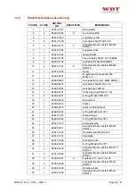
Page 45: ...2480 89024 Drive shaft 1296 18 16 2 8480 99161 Locking ring DIN 471 12x1 17 2 8480 84001 O Ring 100x2 DIN 3771 18 1 2480 82016 Cylinder housing 19 1 2480 84012 Piston 20 1 2480 84015 Piston guide band...

Page 46: ...X Label Release 48 1 5481 03003 X Label A 49 1 5481 02006 X Label P 50 1 5481 03005 X Label P2 51 1 5481 14002 Label Serien Nr 52 2 5480 81027 X Label WDT red 53 2 5481 14001 X Label UP 14 Z black 54...

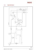
Page 47: ...BDA UP 14 Z 03 15 REV 0 Page 47 71 14 3 Pneumatic Diagram Fig 14 2...

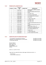
Page 48: ...L screw in connector G1 8 4mm 11 3 8480 88079 X L screw in connector G1 8 6mm 12 1 8480 88100 X Angle out in 1 8 13 1 8480 88073 X Exhaust throttle muffler 1 8 14 1 8480 88063 X Compressed air muffler...

Page 49: ...d indentification 56 4 3 Donn es Techniques 56 4 4 Protection de S curit 56 4 5 L Interrupteur d Arr t 57 5 Transport et Mise en Place 57 5 1 Transport 57 5 2 Mise en Place 57 6 Mise en Service Raccor...

Page 50: ...rmit La machine ne doit tre utilis e que dans le but d crit dans le mode d emploi Le constructeur et ou le fournisseur d cline toute responsabilit pour les dommages dus une utilisation non conforme le...

Page 51: ...observ es Les normes de s curit nationales concernant l ge l gal minimum pour l utilisation de Machine pneumatique Sertir UP 14 Z doivent tre respect es Il est strictement interdit de permettre l acc...

Page 52: ...ecouvert Faites preuve de prudence lorsque la Machine pneumatique Sertir UP 14 Z est en marche La Machine pneumatique Sertir UP 14 Z ne doit pas tre utilis e sans couple de matrices et Protection de S...

Page 53: ...machine Pour garantir une bonne compr hension de la formation concernant la machine il convient que cette formation soit donn e dans la langue du personnel de service Qualifications n cessaires du pe...

Page 54: ...e d emploi Pour un transport futur et pour l entreposage conservez l emballage original Dimension Carton 1 Machine et Black box Longueur 380 mm Largeur 340 mm Hauteur 390 mm Poids total ca 15 5 kg Dim...

Page 55: ...Sertir UP 14 Z 02 Protection pour les doigts 03 Raccord des positionneurs 04 L Interrupteur d Arr t 05 P Air comprim 06 A Pression de commande 07 P2 Air comprim commande pied 08 Plaque d identificati...

Page 56: ...14 kN Niveau sonore 73 dB A 4 4 Protection de S curit La Machine Sertir UP 14 Z dispose d une protection de s curit sp ciale contenu de la livraison Selon l application des matrices avec 1 ou sans 2...

Page 57: ...e pneumatique Sertir UP 14 Z sur une surface plane et assurez vous de sa stabilit Assurez vous que la surface est assez robuste pour supporter le poids de la machine dans des conditions d utilisation...

Page 58: ...nement pneumatique D branchez l alimentation pneumatique avant de remplacer la protection de s curit et le couple des matrices AVERTISSEMENT La Machine pneumatique Sertir UP 14 Z ne doit tre mont e et...

Page 59: ...e tuyau d air comprim P de la bo te noire avec le raccord P la machine PU tuyau 6 4 mm Utilisez la Machine pneumatique Sertir UP 14 Z seulement avec d air comprim conditionn huil et filtr Filtre stand...

Page 60: ...vaux avec la Machine pneumatique Sertir UP 14 Z ne porter ni v tements amples ni pendentifs ni cheveux d tach s qui risqueraient d tre happ s par les pi ces de la machine Travaillez avec pr caution Un...

Page 61: ...positionneurs 2 et serrez la vis 3 Enfilez le positionneur au raccord des positionneurs 2 AVERTISSEMENT La grande ouverture de la protection de s curit peut tre utilis e uniquement avec raccord des p...

Page 62: ...hine Il faut garantir un acc s d gag aux l ments de commande de la machine Ceci vaut particuli rement pour la commande pied L utilisation de la machine n est autoris e qu avec la pression air comprim...

Page 63: ...on ne doivent tre effectu es que par le personnel autoris et form cette activit Les carters et les recouvrements en particulier ne doivent tre enlev s que par un personnel qualifi Lors de travaux avec...

Page 64: ...appropri s pendant les op rations de graissage Respectez les consignes de s curit pr sent es dans la fiche de s curit de la graisse Nettoyage et entretien r guliers des parts de la machine qui peuven...

Page 65: ...form cette activit Les carters et les recouvrements en particulier ne doivent tre enlev s que par un personnel qualifi Lors de travaux avec la Machine pneumatique Sertir UP 14 Z ne porter ni v tements...

Page 66: ...ration ne doivent tre effectu es que par le personnel autoris et form cette activit Les carters et les recouvrements en particulier ne doivent tre enlev s que par un personnel qualifi Lors de travaux...

Page 67: ...BDA UP 14 Z 03 15 REV 0 Page 67 71 14 Diagramme et Liste des Pi ces D tach es 14 1 Diagramme des Pi ces D tach es Fig 14 1...

Page 68: ...DIN913 14 1 8480 89037 Douille de Cylindre 16 12 x12 15 1 2480 89024 Onde articulaire 1296 18 16 2 8480 99161 Circlip DIN 471 12x1 17 2 8480 84001 Joint torique 100x2 DIN 3771 18 1 2480 82016 Tube cy...

Page 69: ...rschutz 46 1 5480 81005 X Etiquette Warnung vor Handverletzungen 47 1 5481 14003 X Autocollant Release 48 1 5481 03003 X Autocollant A 49 1 5481 02006 X Autocollant P 50 1 5481 03005 X Autocollant P2...

Page 70: ...BDA UP 14 Z 03 15 REV 0 Page 70 71 14 3 Sch ma pneumatique Fig 14 2...

Page 71: ...nnecteur G1 8 4mm 11 3 8480 88079 X L visser connecteur G1 8 6mm 12 1 8480 88100 X querre ext rieur et int rieur 1 8 13 1 8480 88073 X Air extrait amortisseur de son 1 8 14 1 8480 88063 X Amortisseur...

Reviews: