background image

 2

0


ATTACHMENT TO STRUCTURAL WALLS 

Wall mounted track systems are typically used when it is not possible to hang from the existing ceiling. 

Special consideration is required when fastening wall brackets to the walls. Wall mounted brackets can 

only be attached to structural load-bearing walls. (See Figure 10 – Wall Mount Bracket). There are a 

number of different types of structural walls, each requiring a specific anchor type. Extra care should be 

taken when preparing to attach each bracket. Use a laser to make sure the brackets will be level. If the 

track system is an XY configuration, make sure that the brackets are evenly spaced between parallel 

tracks, as to prevent any potential for the gantry to bind. 

ATTACHING TO CINDERBLOCK: 

There are three anchoring options when attaching to cinderblock walls. 

1.


Epoxy anchors can be used in any hollow portion of the block, as well as through the mortar. Refer

       to the manufacturer specs for application instructions and cure times. Remember that the epoxy                                                        


must cure 100% before a load test can be performed on the track system.

2. Sleeve anchors or lag shield anchors can be used, but are not recommended if the track span

exceeds (a) 92” with Single Track (b) 149” with Double Track (c) 262” with Triple Track. These

anchors are intended for use in hollow blocks.

3. The mounting bracket can be attached by drilling through the structural wall and using a back plate

on the opposite side of the wall. A back plate is simply a small steel plate (1/4” thick) with mounting

holes that mirror the holes on the mounting bracket. The plate should be painted to match the

colour of the wall. Connect the plate to the bracket using long bolts or threaded rod. In the rare

event that the opposite side of the wall is a room that is also being tracked, and the position of the

back plate is a suitable location to mount, a mounting bracket can be used instead of a back plate.

GoLift 

Installation Manual Rev. 27-Mar-2017  

Summary of Contents for GoLift

Page 1: ...GoLift Installation Manual Rev 27 Mar 2017 1 GoLift Hoist INSTALLATION GUIDANCE...

Page 2: ...ETE SLAB 12 ATTACHING TO HOLLOW CORE CONCRETE OTHER HOLLOW STRUCTURE 15 ATTACHMENT TO STEEL I BEAMS 18 ATTACHMENT TO OPEN STEEL WEB JOISTS 19 ATTACHMENT TO STRUCTURAL WALLS 20 ATTACHING TO CINDERBLOCK...

Page 3: ...ing which has led to the enforcement of more strict lifting regulations Wealden Rehab strives to consistently provide exemplary service design and installation to all of its customers In an ever more...

Page 4: ...ttachment Between Wood Joists 3 Attachment to T G I s 4 Attachment to Concrete 5 Attachment to Open Steel Web Joists 6 Attachment to Steel I Beams 7 Attachment to Structural Walls 8 Attachment to Non...

Page 5: ...700 lbs If the lift capacity is greater than 700 lbs the Top Down Method must be used and the minimum joist requirement is 2 x 6 There are two methods than can be used to attach track across wood joi...

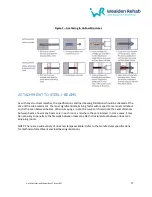
Page 6: ...6 Figure 1 Top Down Wood Joist Installation GoLift Installation Manual Rev 27 Mar 2017...

Page 7: ...7 GoLift Installation Manual Rev 27 Mar 2017...

Page 8: ...ottom Up Wood Joist Installation BOTTOM UP METHOD This method is used when the joists are located between floors and where there is no workable access above the ceiling GoLift Installation Manual Rev...

Page 9: ...e no limitations on lifting capacity If there is workable space above the ceiling use the Top Down Method as described in the previous section If there is no workable space above the ceiling The Botto...

Page 10: ...d to turn a non structural member into a structural member by significantly increasing the pullout value There are instances when the shape of the I joist will limit the materials that can be used for...

Page 11: ...igure 3 Packing T G I joists If the attachment point is biased toward either side of center the weight will not be evenly distributed among the joists This will decrease the pullout value of the membe...

Page 12: ...is value before deciding that the combination of anchor and concrete will be sufficient for the requirements of the lift If there is any doubt as to the adequacy of either the concrete or the concrete...

Page 13: ...13 Figure 4 Multiple Anchor Attachments GoLift Installation Manual Rev 27 Mar 2017...

Page 14: ...14 Figure 5 Concrete Slab Installation GoLift Installation Manual Rev 27 Mar 2017...

Page 15: ...oured reinforced concrete pre cast concrete sections or Beam Block Construction Beam and Block only on new builds or where access is available to visually inspect the beam See Figure 6 Epoxy Anchors i...

Page 16: ...16 Figure 6 Epoxy Anchors in Hollow Core Concrete GoLift Installation Manual Rev 27 Mar 2017...

Page 17: ...pan between beams When surveying a room the surveyor should note the exact distances between beams how many beams are in each room and where they are located In some cases it may be necessary to penet...

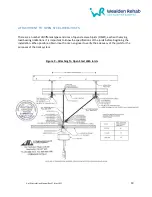
Page 18: ...18 Figure 8 Attaching to Steel I Beams GoLift Installation Manual Rev 27 Mar 2017...

Page 19: ...arying load bearing limitations It is important to know the specifications of the joists before beginning the installation When possible obtain input from an engineer to verify the adequacy of the joi...

Page 20: ...as well as through the mortar Refer to the manufacturer specs for application instructions and cure times Remember that the epoxy must cure 100 before a load test can be performed on the track system...

Page 21: ...nchor length In other words a concrete anchor that is inserted horizontally into concrete will undergo sheer stress as the load is vertical ATTACHING TO STUD WALLS Wood studs are considered to be stru...

Page 22: ...22 Figure 10 Wall Mount Bracket Note Brackets can only be fixed to solid walls GoLift Installation Manual Rev 27 Mar 2017...

Page 23: ...borne by the post itself In other words the load is transferred down the post and is absorbed by the floor LOAD TESTING After the installation is complete the system must be load tested to 125 of the...

Page 24: ...ck Span Lift Capacity kg st Regular Track cm Double Track cm Triple Track cm 181 28 233 378 665 318 50 152 270 480 454 72 110 236 420 Note Any ceiling track must have a minimum 3 brackets Recommended...

Page 25: ...ptions for the installation An adaptation that is being planned can be designed around the angles of the turntable For instance a turntable in a bathroom could be positioned so as to allow transfer be...

Page 26: ...n installing a turntable the turntable should fitted first and the track then fitted from the turntable Curves that come directly from a turntable must not be cut back past the straight section otherw...

Page 27: ...l between an H System travelling track and a fixed track A low maintenance mechanical device the transition gate has a double failsafe action to ensure that the gate will only open when the two tracks...

Page 28: ...28 Track References Closed Gate Open Gate Transfer Gate and Track Components GoLift Installation Manual Rev 27 Mar 2017...

Page 29: ...nections are in line with the current state or local regulations All wiring should be done in such a manner that it is agreeable with the client It is advisable to consult the client as to the positio...

Reviews: