background image

If you are installing Weather Guard® Remote Keyless Entry 

(RKE), only one wiring harness installation is applicable 

based on the vehicle you are installing (check diagrams on 

page 10).

For installing the Weather Guard® Remote Keyless Entry 

Upgrade Kit PS8400 or PS8401, please follow one wiring 

harness installation section that is applicable for your vehicle 

and the Remote Keyless Entry Upgrade Kit installation of the 

instruction manual.

For installation of the truck box to the truck bed, please 

reference the Weather Guard® saddle box installation 

manual, included in the separate accessory/installation kit 

box with your truck box.

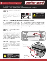
NOTICE: Before you start the installation, please make sure to park the truck on a  level surface, 

turn off the truck engine, and remove the key from the ignition.

!

PS8400: To be used with Chevrolet/GMC/RAM Trucks with 

the factory trailer towing packages. For Chevrolet/GMC/RAM 

trucks without the factory trailer towing package, use 

PS8401

WEATHERGUARD.COM

INSTALLATION GUIDE

Scan to watch installation video

FOR REMOTE KEYLESS ENTRY

ATTENTION: PLEASE READ AND UNDERSTAND ALL INSTRUCTIONS AND WARNINGS

BEFORE ASSEMBLING, INSTALLING OR USING THIS PRODUCT

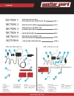
MODEL:   DESCRIPTION:

PS8400  


HITCH WIRE HARNESS

PS8401  


FUSE WIRE HARNESS

PS8402  


4-WAY WIRING HARNESS

PS8403  


SINGLE EXTENSION

PS8404   


SINGLE EXTENSION

Summary of Contents for PowerSync

Page 1: ...ed in the separate accessory installation kit box with your truck box NOTICE Before you start the installation please make sure to park the truck on a level surface turn off the truck engine and remove the key from the ignition PS8400 To be used with Chevrolet GMC RAM Trucks with the factory trailer towing packages For Chevrolet GMC RAM trucks without the factory trailer towing package use PS8401 ...

Page 2: ...S LIST RKE Low side 1 Keyfob 2 Velcro Strips 2 3 Controller 4 Actuator 5 Power Cable 6 Actuator Cable 7 Actuator Linkage 8 Rod Latch Clamp 9 Bridge Bracket 10 Linkage Cover 11 Actuator Cover Screws 6 32 x 1 4 Philips head 2 10x3 4 Philips head 3 8x1 2 Hex Head 6 1 Keyfob 2 Controller 3 Velcro Strips 4 Dual Loop cable 5 Actuator 6 Power Cable 7 Actuator Cable 8 Lock Cam 9 4 40 Shoulder bolt 1 10 Co...

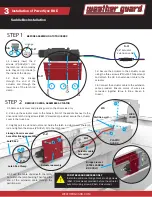
Page 3: ...ute the new harness between the rear bumper and the knock out hole in the bulkhead of the truck bed It is usually easiest to follow the path of an existing wiring harness along the frame of the truck recommend driver side Secure the new harness to the truck in a few locations using the zip ties supplied ROUTE HARNESS INTO TRUCK BOX AND CONNECT Remove the knock out plug from the bulkhead of the tru...

Page 4: ...the truck bed feed the harness end into the truck bed and then through the grommet in the side of the truck box RECONNECT THE BATTERY DISCONNECT BATTERY Disconnect the negative terminal from the truck s battery CONNECT NEW TRUCK BOX HARNESS TO TRUCK FUSE BOX AND GROUND A If you are utilizing a slot currently in use as in the case of the horn slot remove the existing fuse select the fuse with 10 am...

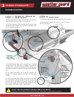
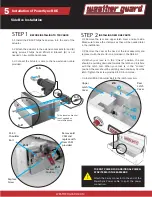
Page 5: ...3 Secure the actuator to the actuator cover using the three screws 10x3 4 Phillips Head and attach the 28 inch extension cable to the actuator 2 2 Line up the actuator cover to the holes in front of the saddle box next to the driver side latch Using screws 8x1 2 Hex Head provided secure the actuator cover to the truck box 2 3 Lightly pull to extend actuator end Guide the latch rod clamp over the l...

Page 6: ...le to PowerSync power cable Use 4 way connector if needed PowerSync Power cable enters box here TO SPLIT POWER FOR ADDITIONAL POWERSYNC ITEMS IN THE SAME BOX Attach the 4 way connector to the end of the PowerSync Power cable to split the power connection Controller 3 3 Route the Power cable on the connector down the guide channel where the Gas Strut is installed Connect the controller power cable ...

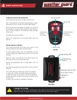
Page 7: ...additional Keyfob enter Learning Mode by locat ing and pressing the programming button 3x until red LED activates Press any button on each keyfob 1 time LED indicator will flash with each fob and then remains solid System will automatically exit Learning Mode within 30 seconds If pairing and testing the keyfob s does not work check the following First try the pairing procedure again If still unsuc...

Page 8: ...Unlock position the cam should be pointing down and towards the latch and interfere with the latch cam When your lock is in the Locked position the cam should be pointing down and away from the latch Tighten the screw provided to 80 in lb torque 2 4 Install 4 40 Shoulder Bolt to the latch lever arm Side Box Installation INSTALLING NEW RKE PARTS 1 1 Install the 8 16 Philips head screw into the end ...

Page 9: ...OLLER AND PAIRING THE KEYFOB STEP 4 PowerSync Power Cable Connects to Connector Power Extension Controller Actuator Cable Extension Controller Power Cable Actuator Cable Connector 4 4 Once programed the actuator should pull on the latch rod Once verified and with the keys to your box nearby close the truck box lid and press the button on the key fob The truck box lid will open Use the provided Vel...

Page 10: ...ync which has a 3 year warranty Please call our customer service department toll free at 1 800 456 7865 with any questions or comments DO NOT use these products for storing or transporting flammables explosives hazardous materials or waste such as gasoline solvents gun powder dynamite gases or any tanks torches or gas powered equipment These products are intended and safe for storing and transport...

Reviews: