11
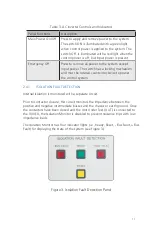
Table 3. AC Inverter Controls and Indicators
Panel Functions
Description
Main Power On/Off
Press to apply and remove power to the system.
The switch ON is illuminated with a green light
when control power is applied to the system. The
switch OFF is illuminated with a red light when the
control power is off, but input power is present.
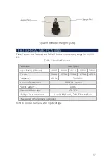
Emergency Off
Press to remove all power to the system except
input power. The switch has a locking mechanism
and must be rotated counterclockwise to power
the control system.
2.4.1 ISOLATION FAULT DETECTION
Internal Isolation is monitored with a separate circuit.
Prior to contactor closure, this circuit monitors the impedance between the
positive and negative intermediate busses and the chassis or earth ground. Once
the contactors have been closed and the Unit Under Test (UUT) is connected to
the 900 EX, the Isolation Monitor is disabled to prevent nuisance trips with low
impedance loads.
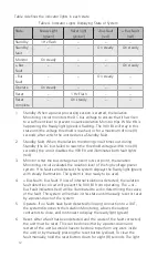
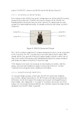
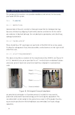
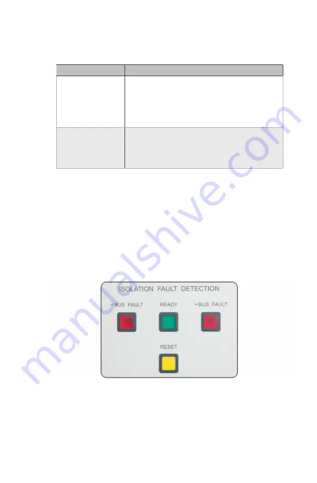
The Isolation Monitor has four indicator lights (i.e., Ready, Reset, - Bus Fault, + Bus
Fault) for displaying the state of the system (see Figure 3).
Figure 3. Isolation Fault Detection Panel
Summary of Contents for 900EX
Page 1: ...Installation Operation and Maintenance Manual EV Test Systems 900 EX ...
Page 6: ...iv ...
Page 7: ...Chapter 1 Introduction ...
Page 11: ...Chapter 2 System Description ...
Page 25: ...Chapter 3 Installation ...
Page 29: ...Chapter 4 Operation ...
Page 48: ...42 ...
Page 49: ...Chapter 5 Maintenance ...
Page 53: ...Appendix A Glossary of Terms ...
Page 58: ...52 ...
Page 59: ...Appendix B DC I O Connector Assembly ...
Page 63: ...Appendix C 900 EX Remote Voltage Sense Operation ...
Page 66: ...60 ...
Page 67: ...Appendix D High Voltage Interlock Wiring ...
Page 69: ...Appendix E Index ...
Page 72: ...22855 03 04 ...


