15
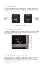
system. The ROS PC connects via RS-232 to the 900 EX (see Figure 7).
2.5.1.3 HV INTERLOCK (FRONT PANEL)
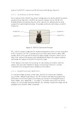
Each channel of the 900 EX has a High Voltage Interlock Switch (HVIS) for added
protection (see Figure 6). The HVIS can put one channel of the 900 EX into
Standby Mode without affecting the other channel. It is designed to be used
as part of an automated test setup. For parallel and multi-unit modes, use HVIS
Channel A.
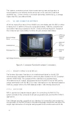
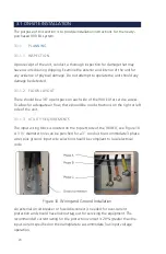
Figure 6. 900 EX Connector Pinouts
Pin 1 (+V) is a system su5V isolated voltage source that is to be connected
to Pin 2 (+sense). The Pin 3 (-sense) has to be connected to the Pin 4 (the GND
signal), which is the ground of the (+V) isolated supply. A break in either one of
these links will put that channel into Standby Mode (open the output contactor
and isolate the output of the 900 EX from the load).
If this feature is not used, it is necessary to have mating connectors with the
jumper wire provided installed for proper functioning of the unit. Contact
Customer Service Department for additional information.
2.5.1.4 REMOTE VOLTAGE SENSE (RVS)
To increase voltage accuracy at the Load, the 900 EX can provide feedback
on a remote voltage measurement. The RVS mode is activated by pressing the
RVS button on the front panel. This feature can be used in Voltage Mode and
Power Mode. (See “Appendix C” on page 57 for proper wiring and use of this
feature.) In Current and Resistance Modes, the remotely measured voltage will be
displayed once the RVS Mode is enabled.
Summary of Contents for 900EX
Page 1: ...Installation Operation and Maintenance Manual EV Test Systems 900 EX ...
Page 6: ...iv ...
Page 7: ...Chapter 1 Introduction ...
Page 11: ...Chapter 2 System Description ...
Page 25: ...Chapter 3 Installation ...
Page 29: ...Chapter 4 Operation ...
Page 48: ...42 ...
Page 49: ...Chapter 5 Maintenance ...
Page 53: ...Appendix A Glossary of Terms ...
Page 58: ...52 ...
Page 59: ...Appendix B DC I O Connector Assembly ...
Page 63: ...Appendix C 900 EX Remote Voltage Sense Operation ...
Page 66: ...60 ...
Page 67: ...Appendix D High Voltage Interlock Wiring ...
Page 69: ...Appendix E Index ...
Page 72: ...22855 03 04 ...


