49
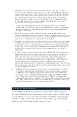
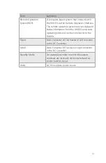
Term
Definition
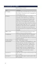
DC Converter
A subassembly of the 900 EX on the right side
of the cabinet. Consists of two independently
controllable converters (A and B), each
regulating the output (load) terminals based
on front panel settings or commands from a
remote operation system.
DC I/O Connector
Use 350MCM cables, rated 1000VAC,
connected to (-) and (+) marked terminals,
per channel for NO CAMLOCKs unit. For
CAMLOCKs unit, use ECT 17DSS-350M
Connectors in black and red. See Appendix B
for instructions.
Grounding
The 900 EX must be connected to an
equipment-grounding conductor that is run
with the circuit conductors. Connections must
comply with Chapter 2 and the Electromagnetic
Interference Section of ANSI/IEEE Standard 142-
199, “Recommended Practice for Grounding
of Industrial and Commercial Power Systems,”
Section 250 (Grounding) of NEC, and all local
codes and ordinances. Webasto recommends
no more than 0.1 Ohms between all equipment
and ground. Use copper conductors and
terminal lugs only.
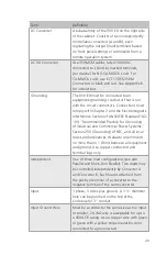
Independent
One of three load configurations (see also
Parallel and Multi-Unit Parallel). Two loads may
be controlled independently by Converter A
and Converter B. Each load is attached from
the positive terminal of a converter to the
negative terminal of the same converter.
Input
3 phase, 3 wires plus ground. A 3 ½" diameter
hole can be punched on the top of the
enclosure for 3" conduit.
Input Ground Wire
Must be a conductor the same size as the input
or smaller; 2 AWG wire is acceptable for up to
a 450A CB rating. Use a copper wire with green
or green with a yellow stripe insulation color
connected to a ground stud.
Summary of Contents for 900EX
Page 1: ...Installation Operation and Maintenance Manual EV Test Systems 900 EX ...
Page 6: ...iv ...
Page 7: ...Chapter 1 Introduction ...
Page 11: ...Chapter 2 System Description ...
Page 25: ...Chapter 3 Installation ...
Page 29: ...Chapter 4 Operation ...
Page 48: ...42 ...
Page 49: ...Chapter 5 Maintenance ...
Page 53: ...Appendix A Glossary of Terms ...
Page 58: ...52 ...
Page 59: ...Appendix B DC I O Connector Assembly ...
Page 63: ...Appendix C 900 EX Remote Voltage Sense Operation ...
Page 66: ...60 ...
Page 67: ...Appendix D High Voltage Interlock Wiring ...
Page 69: ...Appendix E Index ...
Page 72: ...22855 03 04 ...


