


62
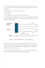
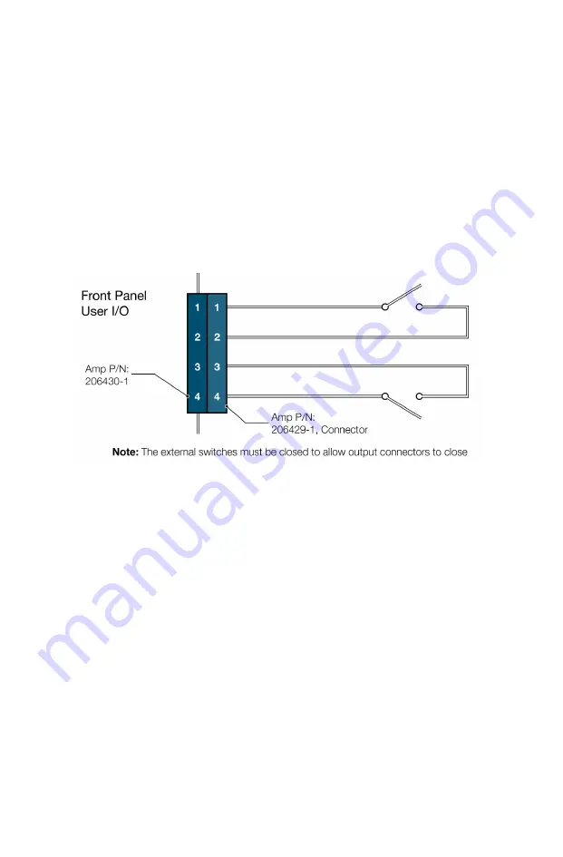
The wiring diagram in Figure 27 shows how to wire the mating connector for
the HV Interlock provided on the Front Panel User I/O. See below for a list of pin
descriptions:
• Pin 1 (+V) is a system-su5 V voltage source.
• Pin 2 (+sense).
• Pin 3 (-sense).
• Pin 4 (GND) is the ground signal of the +5 V voltage source.
In the Independent Configuration, a break in either one of these links will put that
channel into Standby Mode (open the output contactor and isolate the output of
the 900 EX from the load).
Figure 27. High Voltage Interlock Connector Wiring
In Parallel Configuration, a break in a specific channel’s HV Interlock will open
that channel’s DC Contactor. The firmware will recognize this event and open the
other DC Contactor and put the system into Standby Mode, thus isolating the
output of the 900 EX from the load.
If a true hardware interlock is desired for both channels in Parallel Configuration,
one link in each HV Interlock must be broken at the same time.
Summary of Contents for 900EX
Page 1: ...Installation Operation and Maintenance Manual EV Test Systems 900 EX ...
Page 6: ...iv ...
Page 7: ...Chapter 1 Introduction ...
Page 11: ...Chapter 2 System Description ...
Page 25: ...Chapter 3 Installation ...
Page 29: ...Chapter 4 Operation ...
Page 48: ...42 ...
Page 49: ...Chapter 5 Maintenance ...
Page 53: ...Appendix A Glossary of Terms ...
Page 58: ...52 ...
Page 59: ...Appendix B DC I O Connector Assembly ...
Page 63: ...Appendix C 900 EX Remote Voltage Sense Operation ...
Page 66: ...60 ...
Page 67: ...Appendix D High Voltage Interlock Wiring ...
Page 69: ...Appendix E Index ...
Page 72: ...22855 03 04 ...


