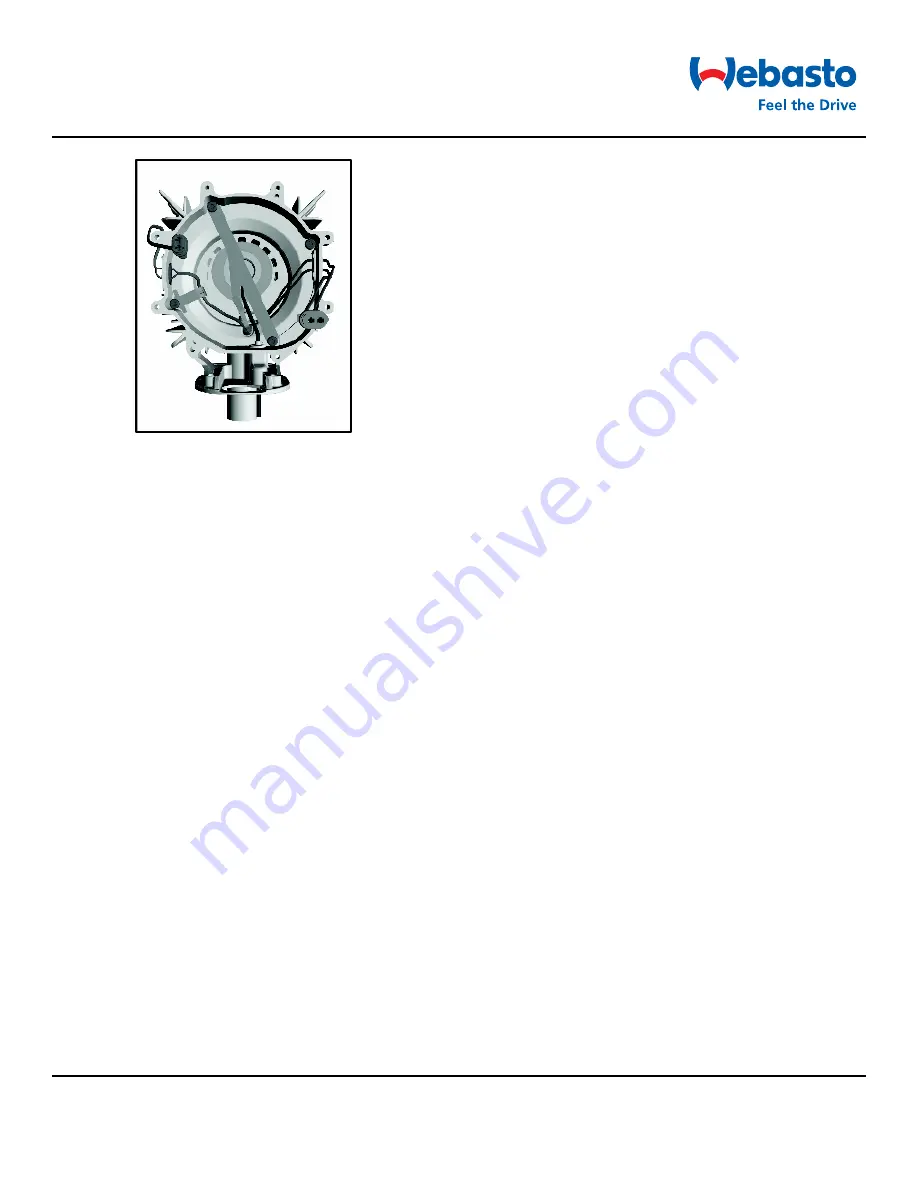
Figure 33: Top view of heat exchanger
4. Install drive unit (see 9.2.6.2).
5. Install control unit (see 9.2.3.2).
6. Fit heating air fan (see 9.2.5.2).
7. Install housing parts (see 9.2.2).
8. Install heater (see 8.7.1.2)
9. Check CO
2
setting and adjust if necessary (see Section 6.3).
9.2.8 Replacing evaporator mount and glow plug
9.2.8.1 Removal
1. Remove heater (see 8.7.1.1).
2. Remove housing parts (see 9.2.1).
3. Remove control unit (see 9.2.3.1).
4. Remove drive unit (see 9.2.6.1).
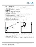
5. Remove 2 screws (1, Figure 34) and take off spring clip (2). Discard spring clip (2).
6. Press grommet of exhaust temperature sensor (10) from outside inward into heat exchanger (6) and remove
exhaust temperature sensor (10).
7. Press grommet of glow plug (8) inward out of heat exchanger housing (6).
8. Press grommet on fuel supply line of evaporator mount (3 or 7) inward out of heat exchanger housing (6).
9. Carefully pull evaporator mount (3 or 7) out of combustion pipe (4). Guide fuel pipe out of heat exchanger
housing (6) by turning evaporator mount.
10. Remove retaining clip (9) and pull glow plug (8) out of evaporator mount (3 or 7).
9.2.8.2 Installation
1. Guide glow plug (8, Figure 34) into evaporator mount (3 or 7) and secure with retaining clip (9) as shown in
Figure 34, Detail A.
IMPORTANT:
During the following work step, make sure that the fuel connection is not bent.
2. Guide evaporator mount into heat exchanger (6). Guide fuel pipe through grommet hole in heat exchanger
(6) and lay evaporator mount on combustion pipe.
3. Press grommet on fuel pipe into the heat exchanger (6).
4. Thread the cable of glow plug (8) through opening in heat exchanger housing (6).
5. Press grommet of glow plug (8) into heat exchanger (6). Ensure that glow plug cables do not form a loop in
heat exchanger (6).
60
Air Top Evo 40 / Air Top Evo 55 Service Manual
Summary of Contents for Air Top Evo 40
Page 63: ...4 2015...


