Troubleshooting – BlueCool Truck Electrical System
www.webasto.us
23
Webasto Product N.A., Inc.
™
5.3
Malfunctions with System in Discharge Mode and Vehicle Key OFF (Sleeper Cooling)
The following table lists the possible malfunctions.
With the vehicle key in the OFF position, check operation of the air-handler by turning both knobs of the control panel
on. A small green LED should illuminate. If the green LED does not illuminate and there is no air circulation through
the air-handler, check fuses and battery connections. Repair as necessary. If this does not remedy the malfunction,
follow the troubleshooting procedures listed in Table 8. If the LED does illuminate but air circulating fans and/or water
pump do not function, follow the troubleshooting procedures listed in Table 8.
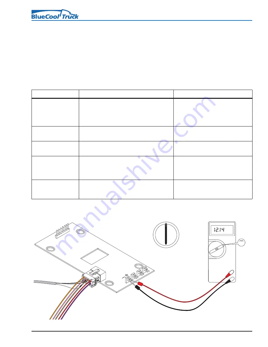
Checking air circulation fan circuits
Figure 28. Air circulation fan circuit checks (variable output DC voltage)
Table 8. Malfunction of components during discharge mode (sleeper cooling) with key OFF
Symptom/Malfunction
Inspection
Remedy
12 volts negative and/or
positive not present at control
module.
Check 10 amp. fuse at fuse holder X2.
Check for power on pin-1 (red wire) and ground on pin-2
(brown wire) of control module connector X1. Refer to Fig. 16,
on pg. 17.
Replace blown/defective fuse.
Damaged or open circuit. Repair wiring or
connections.
No ground connection. Repair wiring or
connections.
No output to circulation fans
at control module.
With fan control turned on, check for output voltage at the 4
2-pin connectors of the control module. Refer to Fig. 28, on
pg. 23.
Replace control module.
One or more circulation fans
not operating.
With fan control turned on, check for power at the 2-pin
connectors on the control module of the suspect fan. Refer to
Fig. 28, on pg. 23.
Power present at 2-pin connector? Replace fan.
Power not present at 2-pin connector? Replace
control module.
Coolant circulation pump not
operating. Control module
malfunction suspected.
With fan control on and cooling control on full, check for
power at pin-4 (orange wire) and ground at pin-2 (brown
wire) at control module connector X1. Refer to Fig. 29, on pg.
24.
Power present at pin-4? Check circulation pump
and wiring.
Power not present at pin-4? Ensure there is a
ground circuit at pin-2. If present, replace control
module.
Coolant circulation pump not
operating. Circulation pump
malfunction suspected.
With fan control on and cooling control on full, check for
power at circulation pump connector X8 (orange wire) and
ground at (brown wire). Refer to Fig. 30, on pg. 25.
Power and ground present? Replace circulation
pump.
Power or ground not present? Open circuit. Repair
or replace harness.
V DC
V
V
Volts DC
_
OFF
ON
ACC
Key Switch
Position
+


