www.webasto.us
15
Webasto Product N.A., Inc.
DBW 2010/2020/300 COOLANT HEATERS
GENERAL DESCRIPTION
2.1.8
C
OUPLING
(4)
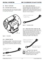
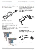
The coupling (clutch) provides the mechanical connection
between the motor and the combustion air fan.
Figure 8:
Motor to Fan Coupling (Clutch)
NOTE:
Before reusing the coupling, it has to
be checked for cracks, wear and the condition
of the flat portion of the center shaft hole. Too
much play on the shaft will result in a load
continuous noise.
2.1.9
T
OOTHED
G
EARING
(6)
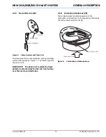
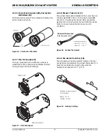
The gears drive the fuel pump with a gear ratio of 1:3.5.
Figure 9:
Fuel Pump Drive Gearing
NOTE:
If signs of wear are showing within the
sector of the toothed gearing as well as at the
flat portion of the shaft hole of the large gear,
the gears will have to be replaced.
2.1.10 F
UEL
P
UMP
(24)
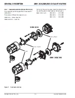
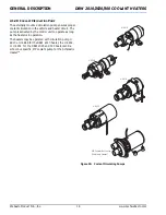
The fuel pump (single-staged toothed gear pump)
delivers the fuel from the tank to the heater and brings it
to a pressure of 10 ± 0.5 bar (145 ± 7 psi) for DBW
2010*, DBW 2020 and DBW 300.
*DBW 2010 equipped with a 0.35 Gal/hr. nozzle only.
For DBW 2010 with 0.40 Gal/hr. nozzle, the fuel
pressure should be set to 8 – 0.5 bar (116 – 7 psi).
Figure 10:
Fuel Pump Assembly
2.1.11 F
UEL
C
ONTROL
V
ALVE
AND
S
OLENOID
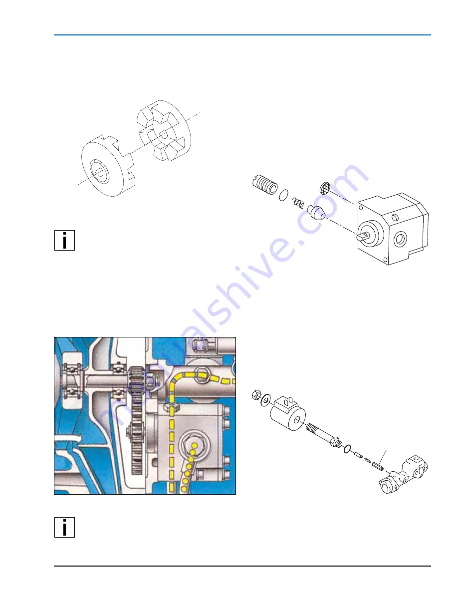
(8)
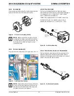
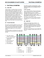
The fuel solenoid valve interrupts the fuel supply to the
atomizer nozzle when the heater is switched off and
during a control pause period. When there is no current
present, the solenoid valve is closed.
Figure 11:
Fuel Solenoid Assembly
Strainer
Pressure
Regulation
Valve
Plunger Valve


