background image

Webasto Product N.A., Inc.

22

www.techwebasto.com

TECHNICAL DATA

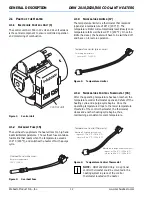
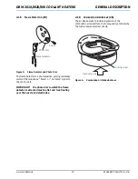
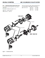
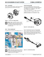
DBW 2010/2020/300 COOLANT HEATERS
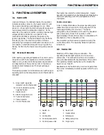
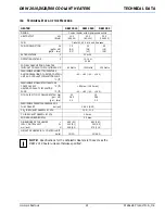
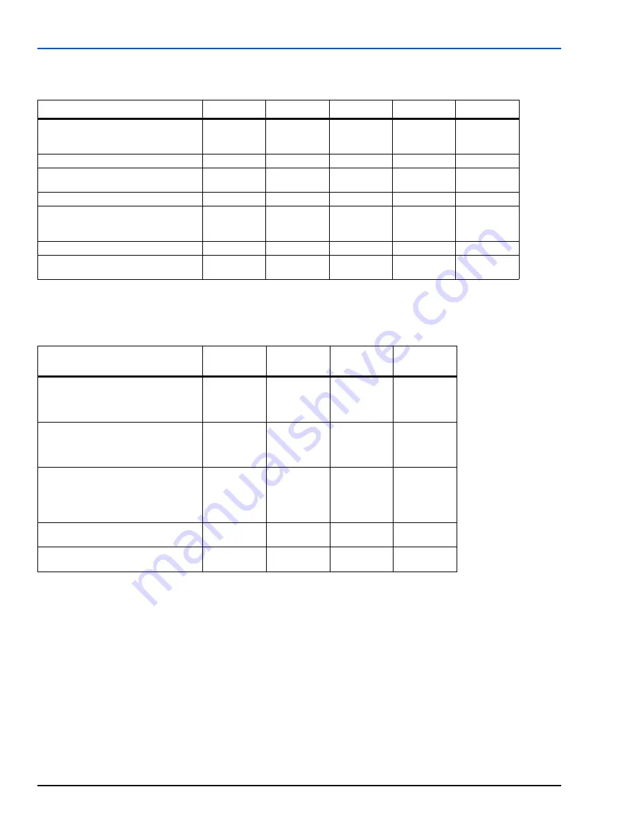
4.2

T

ECHNICAL

 D

ATA


OF


THE

 C

IRCULATING

 P

UMPS

*Choice of circulating pump depends on resistance of coolant circuit.
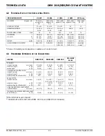
4.3

P

ERMISSIBLE

 E

XTENSION


OF


THE

 C

ONNECTIONS

*Other dimensions upon request.
**Heaters built until model number DBW 2020.31 and DBW 300.10 inclusively.

CIRCULATING PUMP

U 4810

U 4846

U 4814

U 4851

MP Pump

FLOW RATE

l/h (gal/h – US)

1600 (7.0)

against 0.15 

bar

1650 (7.26)

against 0.15 

bar

5200 (22.9)

against 0.2 bar

6000 (26.4)

against 0.4 bar

3406 - 4542 

(15 - 20)

NOMINAL VOLTAGE

12 or 24

12 or 24

12 or 24

24

12

OPERATING VOLTAGE

10-14 or

20-28

10-14 or

20-28

10-14 or

20-28

20-28

10-14

POWER CONSUMPTION

Watt

25

30

104

209

72

DIMENSIONS

L

mm (inch)

W

H

166 (6.5)

94 (3.7)
77 (3.0)

180 (7.0)

74 (2.9)

112 (4.4)

248 (9.76)

100 (3.9)

106 (4.17)

285 (11.22)

115 (4.53)
118 (4.64)

214 (8.42)
106 (4.16)
106 (4.16)

WEIGHT

kg (lb)

0.8 (1.8)

22 (48.5)

2.1 (4.6)

2.8 (6.17)

2.5 (5.5)

RECOMMENDED FOR HEATER*

DBW 2010

DBW2010

DBW 2020
DBW   300

DBW 2020
DBW   300

Scholastic

Heater™

HEATER

DBW 2010

DBW 2020

DBW 300

Scholastic 

Series

FUEL LINE:
internal diameter

mm (inch)

maximum length

m (ft)

suction head

m (ft)

6* (0.25)

10 (33)

2 (6.6)

6* (0.25)

10 (33)

2 (6.6)

6* (0.25)

10 (33)

2 (6.6)

6* (0.25)

10 (33)

2 (6.6)

COMBUSTION AIR INTAKE PIPE:
internal diameter

mm (inch)

maximum length

m (ft)

maximum degree of bends total

m (ft)

80 (3.2)
5 (16.5)

270°

80 (3.2)
5 (16.5)

270°

80 (3.2)
5 (16.5)

270°

80 (3.2)
5 (16.5)

270°

EXHAUST PIPE:
internal diameter

mm (inch)

maximum length

m (ft)

maximum degree of bends total

m (ft)

38 (1.5)

5 (16.5)

270°

70 or 80**

(2.75 or 3.2**)

5 (16.5)

270°

70 or 80**

(2.75 or 3.2**)

5 (16.5)

270°

38 (1.5)

5 (16.5)

270°

HOSE CONNECTIONS - INLET/OUTLET
outside diameter

mm (inch)

18 (0.75)

38 (1.5)

38 (1.5)

25 (1.0)

TEMPERATURE DIFFERENCE BETWEEN INLET 
and OUTLET

 (ΔΤ)

°C (°F)

10 (18)

10 (18)

10 (18)

10 (18)

Summary of Contents for DBW 2010

Page 1: ...pair a Webasto heating or cooling system unless you have successfully completed the factory training course and have the technical skills technical information tools and equipment required to properly complete the necessary procedures ALWAYS carefully follow Webasto installation and repair instructions and heed all WARNINGS Webasto rejects any liability for problems and damage caused by the system...

Page 2: ......

Page 3: ...8 15 2 1 12 Fuel Nozzle and Nozzle Holder 14 16 2 1 13 Fuel Line Connections 25 16 2 1 14 Electronic Ignition Unit 3 16 2 1 15 Ignition Electrodes 13 16 2 1 16 Combustion Chamber 20 Combustion Air Swirler 21 17 2 1 17 Heat Exchanger 19 17 2 1 18 Preheat Thermostat 7 17 2 1 19 Pre heater Cartridge 10 17 2 1 20 Coolant Circulating Pump 18 3 Functional Description 19 3 1 Switch ON 19 3 2 Heating Oper...

Page 4: ...6 Scholastic Heater 12 V with 7 Day Timer Model 1529 40 7 7 Scholastic Heater 12 V with 7 Day Timer Model 1531 41 7 8 Control Unit Identification of Terminals 42 8 Servicing 43 8 1 General 43 8 2 Heater Servicing 43 8 3 Vehicle Servicing 43 8 4 Heater Test Run 43 8 5 Maintenance 43 8 5 1 Burner Head Opening and Closing 43 8 6 Visual Inspections and Regulations for Installation 45 8 6 1 Connection ...

Page 5: ... 2 4 2 Installation 51 9 2 5 Burner Replacement 51 9 2 5 1 Removal 51 9 2 5 2 Installation 51 9 2 6 Fuel Valve and Solenoid Replacement 53 9 2 6 1 Removal 53 9 2 6 2 Installation 53 9 2 7 Fuel Pump Replacement 53 9 2 7 1 Removal 53 9 2 7 2 Installation 53 9 2 8 Fuel Nozzle Replacement 54 9 2 8 1 Removal 54 9 2 8 2 Installation 54 9 2 9 Flame Detector Replacement 54 9 2 9 1 Removal 54 9 2 9 2 Insta...

Page 6: ...Repair 62 9 3 1 Removal 62 9 3 2 Disassembling 62 9 3 3 Assembling 62 9 3 4 Installing 62 9 4 MP School Bus Circulation Pump 64 9 4 1 Removal 64 9 4 2 Disassembling 64 9 4 3 Assembling 64 9 4 4 Installing 64 10 Instruments and Tools 65 10 1 Setting Gauge 65 10 2 Tester 65 10 3 CO2 Test Apparatus 65 10 4 Smoke Number Test Apparatus 65 10 5 Nozzle Wrench 66 10 6 Fuel Pressure Gauge 66 10 7 Grease an...

Page 7: ... of accidents and the relevant operating safety instructions have to be observed at all times General Safety Regulations beyond the scope of these regulations are detailed in the following The specific safety regulations applicable to this manual are highlighted in the individual chapters by Warnings Cautions and Notes 1 5 1 GENERAL SAFETY NOTES The year of first operation must be permanently mark...

Page 8: ...and provisions relating to the installation of the heater in vehicles refer to the installation instructions IMPORTANT Failure to follow the installation instructions and the notes contained therein will lead to all liability being refused by Webasto The same applies if repairs are carried out incorrectly or with the use of parts other than genuine spare parts This will result in the invalidation ...

Page 9: ...ermittently controlled by the temperature control thermostat The heaters DBW 2010 DBW 2020 DBW 300 and Scholastic Heater basically consist of the combustion air intake adjustable the combustion air fan and motor the fuel pump the fuel control valve and solenoid the nozzle holder and nozzle the ignition coil and ignition electrodes the combustion chamber the heat exchanger For control and monitorin...

Page 10: ...g clutch 5 Combustion air fan 6 Toothed gearing 7 Preheat thermostat blue and green wires 8 Fuel control valve and solenoid 9 Electrode holder 10 Pre heater 11 Coolant outlet 12 Bleeding valve 13 Ignition electrodes 14 Fuel nozzle 15 Overheat fuse white wires 16 Temperature control thermostat green and red wires 17 Temperature limiter green wires 18 Coolant inlet 19 Heat exchanger 20 Combustion ch...

Page 11: ...g 7 Preheat thermostat blue and green wires 8 Fuel control valve and solenoid 9 Electrode holder 10 Pre heater 11 Coolant outlet 12 Bleeding valve 13 Ignition electrodes 14 Fuel nozzle 15 Overheat fuse white wires 16 Temperature control thermostat green and red wires 17 Temperature limiter green wires 18 Coolant inlet 19 Heat exchanger 20 Combustion chamber 21 Combustion air swirler 22 Exhaust out...

Page 12: ... has reset the heater will have to be switched off and back on to restore operation Figure 3 Temperature Limiter 2 1 4 TEMPERATURE CONTROL THERMOSTAT 16 After the operating temperature has been reached the temperature control thermostat opens and shuts off the heating cycle and a purge cycle begins Once the operating temperature drops to the lower temperature threshold of the control thermostat th...

Page 13: ...flame or no flame signal to the control unit IMPORTANT The photo disc to which the flame detector is attached must be flat and free floating over the nozzle and electrodes 2 1 6 COMBUSTION AIR INTAKE 26 The air intake socket provides regulation of the combustion air quantity to the fuel quantity atomized by the high pressure atomizer nozzle Figure 6 Combustion Air Intake Bellows Flame Detector Pho...

Page 14: ...e air necessary for combustion There are two different fan designs in use DBW 2010 lateral canal fan DBW 2020 300 radial fan The motor through a coupling drives the combustion air fan and through a toothed gearing the fuel pump Rated motor r p m DBW 2010 4500 RPM DBW 2020 5000 RPM DBW 300 5800 RPM Figure 7 Combustion Air Fans DBW 2010 DBW 2020 300 Drive motor Fan wheel Cap ...

Page 15: ...of the toothed gearing as well as at the flat portion of the shaft hole of the large gear the gears will have to be replaced 2 1 10 FUEL PUMP 24 The fuel pump single staged toothed gear pump delivers the fuel from the tank to the heater and brings it to a pressure of 10 0 5 bar 145 7 psi for DBW 2010 DBW 2020 and DBW 300 DBW 2010 equipped with a 0 35 Gal hr nozzle only For DBW 2010 with 0 40 Gal h...

Page 16: ...There is no return fuel line on this model Figure 13 Fuel Pumps 2 1 14 ELECTRONIC IGNITION UNIT 3 The electronic ignition unit develops high voltage of approximately 8000 volts to produce a spark at the tips of the ignition electrodes The electronic ignition unit is only in operation during the starting phase IMPORTANT Never switch on the electronic ignition unit without being connected to the ign...

Page 17: ... the burner head on the back wall DBW 2010 or on the photo disc DBW 2020 300 It switches the nozzle holder pre heating element 10 on which warms the fuel inside the nozzle holder to ensure fuel atomization in severe cold conditions Figure 18 Preheat Thermostat 2 1 19 PRE HEATER CARTRIDGE 10 The pre heater is a heating element located in the fuel nozzle holder Operated by the preheat thermostat 7 i...

Page 18: ... and heater circuit The pump is activated by the control unit to operate as long as the heater is in operation The heaters may be operated with circulation pump U 4810 or U 4846 for the DBW 2010 heater the U 4814 or U 4851 for the DBW 2020 and 300 heaters and a school bus specific MP coolant pump for the Scholastic Heater Figure 20 Coolant Circulating Pumps U 4810 U 4846 U 4814 U 4851 MP School Bu...

Page 19: ...ol idle period Heater operation is resumed when the temperature drops below the lower operating point of the temperature control thermostat CONTROL IDLE PERIOD A rise in temperature above the upper operating point makes the solenoid valve in the fuel pump shut off the fuel supply initiating the run down The flame extinguishes the combustion air fan and the circulation pump however continue their o...

Page 20: ...s NOTE The allocation of circulation pumps to heater units must be in accordance with coolant resistances FUEL FOR DBW SERIES DIESEL HEATING OIL KEROSENE Diesel fuel heating oil and kerosene are suitable fuels for the heater The Diesel fuel specified by the vehicle manufacturer is suitable as fuel for the heater Any negative effect caused by additives is not known When the fuel for the heater is d...

Page 21: ...4 or 20 28 POWER CONSUMPTION OF HEATER WITHOUT COOLANT CIRCULATION PUMP 60 Watts 120 Watts 130 Watts PERMISSIBLE AMBIENT TEMPERATURE DURING OPERATION OF HEATER CONTROL UNIT AND COOLANT CIRCULATION PUMP C F 40 60 40 140 PERMISSIBLE STORAGE TEMPERATURE CONTROL UNIT C F HEATER COOLANT CIRCULATION PUMP C F 85 max 185 max 40 85 40 185 MIN CAPACITY OF COOLING SYSTEM liter gal US gal Imp 10 2 65 2 2 15 3...

Page 22: ...2 9 112 4 4 248 9 76 100 3 9 106 4 17 285 11 22 115 4 53 118 4 64 214 8 42 106 4 16 106 4 16 WEIGHT kg lb 0 8 1 8 22 48 5 2 1 4 6 2 8 6 17 2 5 5 5 RECOMMENDED FOR HEATER DBW 2010 DBW2010 DBW 2020 DBW 300 DBW 2020 DBW 300 Scholastic Heater HEATER DBW 2010 DBW 2020 DBW 300 Scholastic Series FUEL LINE internal diameter mm inch maximum length m ft suction head m ft 6 0 25 10 33 2 6 6 6 0 25 10 33 2 6 ...

Page 23: ...ombustion Does Not Take Place Combustion Stops After 30 Seconds Combustion Cannot Be Stopped During Combustion Light Color Smoke During Combustion Dark Color Smoke Heating Unit Overheating E l e c t r i c a l F u s e E l e c t r i c a l H a r n e s s a n d C o n n e c t i o n s I n e r t i a S w i t c h S c h o l a s t i c H e a t e r O n l y O N O F F S w i t c h o r W i r i n g O v e r h e a t F...

Page 24: ...mage to the coil may result TEST RESULTS 1 LED 3 lights and combustion achieved operation normal 2 Combustion achieved but no LED 3 light check flame detector 3 Combustion not achieved and no LED 3 light check fuel nozzle check fuel pressure check for blocked fuel lines dirt or ice check ignition electrodes for damage and set gap E Heater should now be in heating mode and will continue to run unti...

Page 25: ...e heater switch or timer to OFF remove the tester and reconnect the control unit Once done set the switch or timer to ON If the heater or a heater component does not respond the control unit is defective Replace the control unit and retest the heater NOTE Since the heater operates in the 68 C 155 F to 75 C 167 F On to Off Off to On range and the vehicle engine may be hot e g coolant above 75 C 167...

Page 26: ...heater ON does fuse release Feed connection defective Temperature in the cooling cycle too high Voltage too low 18 1V resp 9 0 5V Voltage on motor Voltage across terminal C2 and C5 of control unit Under voltage protection in the control unit has reacted charge battery Control unit defective replace Check feed connections to motor for circuit interruptions Is the large spur gear easily spun Fuel pu...

Page 27: ...ve defective Does fuel nozzle produce good fuel atomization Volume on solenoid valve Fuel solenoid valve defective Voltage on solenoid valve Check feed connections Are ignition electrodes correctly set with gauge Adjust ignition electrodes to correct setting with gauge Fuel in the tank Refill fuel tank Are all fuel lines tightly connected Does the pump deliver fuel Fuel nozzle is blocked replace n...

Page 28: ...n 5 3 7 Does the ignition spark flash over on the high voltage wire Does the ignition spark flash over on the electrode insulation Ignition spark coil defective High voltage wire defective Ignition electrode s defective Possible leakage in fuel suction or return fuel lines resulting in air pockets Does the heater start after repeated starting attempts Does heater reteact at all Continue fault find...

Page 29: ... in the fuel return line Has the correct fuel been used according to the operating instructions Observe the recommendations in the operating instructions Because of the return fuel pressure the flow of the fuel nozzle is too high Let heater burn freely warm up to temp Are the permissible combustion values adjustable see section 10 3 Does the heater continue to smoke after adjustment Motor r p m to...

Page 30: ... continue to smoke Any accumulated fuel in the combustion chamber must be allowed to burn off Does heater continue to smoke Open burner remove combustion chamber are there coke deposits visible in the combustion chamber Clean combustion chamber Replace fuel nozzle Is there current through the switch or timer when switched OFF Does heater continue to run more than 180 sec after switching OFF Do exh...

Page 31: ... 6 2 1 1 SETTING PROCEDURE Measure control unit power supply voltage Operate heater for approximately 5 min Measure CO2 contents and compare with CO2 diagram Figure 21 Combustion Air Fuel Mixture Adjustment Loosen locking screw refer to Figure above and reposition shutter with locking screw until rated value is obtained Tighten locking screw with 1 0 0 5 Nm and apply screw seal varnish to mark new...

Page 32: ...NG NOTE The insulation body of the ignition electrodes must not show any damage Damaged insulation of the electrodes requires their replacement Setting ignition electrodes with a spacing beyond the tolerances shown in Fig 23 may or will cause ignition failures NOTE The ignition electrodes can be set with the setting gauge as shown In addition the front edge of the setting gauge must rest against t...

Page 33: ... Coil Check 6 2 5 FUEL PUMP CHECK A pressure gauge and the tester P N 1302691A is required for performing this test A suitable gauge with a range from 0 to 15 bar 0 to 220 PSI can be procured from your authorized Webasto dealer NOTE The fuel pump and the fuel hoses must be replaced every 5 years CHECK Exchange control unit with tester and swing burner head open see Sec 8 5 1 Remove nozzle Screw pr...

Page 34: ...fuel solenoid button on tester several times You should hear an audible clicking sound indicating that the fuel solenoid valve is functioning If no clicking can be heard valve and or solenoid may require replacement see Sec 9 2 6 6 2 7 NOZZLE BLOCK PRE HEATER CHECK At a temperature of 0 C 32 F the heater cartridge in the nozzle block is activated The heating period depends on the heat reflected wi...

Page 35: ...1 6 4 2 3 4 5 6 7 8 BLUE YELLOW VIOLET GRAY BROWN RED BLACK BROWN RED YELLOW YELLOW 9 VEHICLE IGNITION DASH LAMPS OPTIONAL RED WIRING CABLE TO THE HEATER TO TIMER OPTION P2 2 3 5 1 6 4 2 3 4 5 6 7 8 BLUE YELLOW VIOLET GRAY BROWN RED BLACK BROWN RED YELLOW YELLOW DASH LAMPS OPTIONAL RED WIRING CABLE TO THE HEATER t t t BT BATTERY DS INDICATOR LIGHT E IGNITION ELECTRODES F1 FUSE 20A F2 FUSE 7 5A F3 ...

Page 36: ...NIT HEATER 1 2 3 4 5 6 2 1 1 2 3 4 5 6 7 8 BROWN M B D C E F G H J S1 DS F4 F3 F2 F1 X1 VIOLET t t t A BROWN BROWN BROWN YELLOW RED RED GREEN RED RED RED BROWN BROWN VIOLET WHITE BROWN BROWN BLACK WHITE X2 BLOWER INTERFACE OPTION BT BATTERY DS INDICATOR LIGHT E IGNITION ELECTRODES F1 FUSE 15A F2 FUSE 10A F3 FUSE 15A F4 FUSE 20A HR HEATING ELEMENT fuel pre heater K RELAY fuel pre heater L1 SOLENOID...

Page 37: ...TROL THERMOSTAT green and red wires S4 TEMPERATURE LIMITER green and green wires X1 9 PIN HARNESS CONNECTOR round X2 2 WAY CONNECTOR X3 2 WAY CONNECTOR BROWN BROWN BROWN RED RED RED BT E F G J C B A S1 DS F5 X1 H WHITE GREEN RED BLACK WHITE VIOLET F4 t t BLACK BLUE VIOLET GREEN GREEN GREEN RED ORANGE WHITE BLACK BLUE GREEN YELLOW BROWN BROWN BROWN BLACK BLACK GREEN BROWN ORANGE GREEN BROWN BROWN B...

Page 38: ...ires S3 CONTROL THERMOSTAT green and red wires S4 TEMPERATURE LIMITER green and green wires X1 9 PIN HARNESS CONNECTOR round X2 3 WAY CONNECTOR X3 2 WAY CONNECTOR BROWN BROWN BROWN RED RED RED BT E F G J C B A S1 DS F5 X1 H WHITE GREEN RED BLACK WHITE WHITE WHITE VIOLET F4 t t t WHITE WHITE BLACK BLUE VIOLET GREEN GREEN GREEN RED ORANGE WHITE BROWN BLACK BLUE GREEN YELLOW BROWN BROWN BROWN BLUE BL...

Page 39: ...AME DETECTOR S1 ON OFF SWITCH heater S2 PREHEAT FUEL THERMOSTAT blue and blue wires S3 CONTROL THERMOSTAT green and red wires S4 TEMPERATURE LIMITER green and green wires X1 9 PIN HARNESS CONNECTOR round X2 3 WAY CONNECTOR WHITE WHITE WHITE VIOLET F4 t t t WHITE WHITE WHITE BLACK BLUE VIOLET GREEN GREEN GREEN RED ORANGE WHITE BROWN BLACK BLACK BLUE GREEN YELLOW BROWN BROWN BROWN BLUE BLUE BLACK BL...

Page 40: ...OR round X2 3 WAY CONNECTOR X3 TIMER HARNESS CONNECTOR X4 TIMER CONNECTOR WHITE WHITE WHITE VIOLET F4 t t t WHITE WHITE H WHITE WHITE BLACK BLUE VIOLET GREEN GREEN GREEN RED ORANGE WHITE BROWN BLACK BLACK BLUE GREEN YELLOW BROWN BROWN BROWN BLUE BLUE BLACK BLACK GREEN RED BLUE BLACK ORANGE GREEN GREEN BROWN BROWN BROWN BROWN BROWN BROWN BROWN BROWN BROWN BROWN BROWN RED RED RED RED RED RED BROWN L...

Page 41: ...ECTOR round X2 3 WAY CONNECTOR X3 TIMER HARNESS CONNECTOR X4 TIMER CONNECTOR P2 2 3 5 1 6 4 8 10 4 11 12 2 1 VIOLET GRAY BROWN BROWN RED BLACK WHITE GREEN RED BLACK YELLOW 7 DAY TIMER 1531 X4 X3 VEHICLE IGNITION DASH LAMPS OPTIONAL WIRING CABLE TO THE HEATER WHITE WHITE WHITE VIOLET F4 t t t WHITE WHITE H WHITE BLACK BLUE VIOLET GREEN GREEN GREEN RED ORANGE WHITE BROWN BLACK BLACK BLUE GREEN YELLO...

Page 42: ...attery positive B5 Optional coolant pump control input B6 Control light Operation indicator CONNECTOR BLOCK C C1 To temperature control thermostat C2 To Blower motor C4 To overheat fuse temperature limiter and fuel solenoid valve C5 For all heater components C6 Flame detector C7 From normally closed control thermostat C8 To ignition coil Control thermostat with white and orange wires Closes at 60 ...

Page 43: ...haust outlet for contamination and clean as required outside the heating season the heater should be operated with the vehicle engine cold approximately every four weeks for 20 minutes setting the heating system to warm This avoids difficulties in the start up at least once a year in case of contaminated fuel more often the fuel filter or filter cartridge as well as the filter screen of the fuel p...

Page 44: ... DBW 2020 300 7 5 8 5 Nm 66 75 lb in 4 Reconnect electrical connections to the control unit Figure 34 Burner Head Attachment 1 2 3 4 NOTE Depending on the burner head direction of swing the cotter pin may be located to the opposite side 1 Cotter pin 2 Hinge Bolts 2 3 Nut 2 4 Burner head CAUTION Always use hinge bolts to lock burner head in place ...

Page 45: ...y must at least meet the specifications of DIN73379 1C type 3 Fuel hoses must not be kinked or twisted and must be secured with clamps every 25 cm 10 in Also fuel lines may be used consisting of materials standard in the manufacturing of vehicles e g steel or plastic lines made of unhardened light and temperature stabilized PA11 or PA12 e g Mecanyl RWTL according to DIN 73378 observing the applica...

Page 46: ...x bend 270 As an alternative an exhaust deflector can be installed when cleared by Webasto 8 7 REMOVAL AND INSTALLATION CAUTION In installed condition only the following disassembly or removal procedures are permitted should enough space for removal allow such action replacement of temperature limiter replacement of temperature control thermostat replacement of overheat fuse replacement of burner ...

Page 47: ... voltage Prior to replacement of flame detector disconnect electrical connectors of cable harness in vehicle to avoid lethal accidents 8 7 8 COMBUSTION CHAMBER REPLACEMENT NOTE The replacement procedure for the combustion chamber is identical with the heater installed or removed Perform replacement in accordance with 9 2 17 WARNING The heater operates on high voltage Prior to replacement of combus...

Page 48: ...l self resetting and repeat complete bleeding procedure NOTE The heater may be equipped with an automatically resetting temperature limiter The manual reset is not necessary 8 8 2 FUEL SUPPLY SYSTEM BLEEDING When switching the heater on the fuel pump pulls fuel from the fuel tank to prime the complete fuel supply system Should no combustion be achieved with the first start attempt switch the heate...

Page 49: ...1 1 WORK ON COMPONENTS AFTER DISASSEMBLY CAUTION All gaskets located between disassembled components must always be discarded and replaced with new gaskets 9 1 1 1 VISUAL INSPECTION GENERAL Examine all components for damages cracks deformation wear etc and replace as necessary Examine connectors and wiring for corrosion loose contacts wrong crimping etc and repair as necessary Check terminals for ...

Page 50: ...connect electrical connection to overheat fuse at connector block 2 Turn counterclockwise to remove overheat fuse item1 Fig 36 from dry well 9 2 1 2 INSTALLATION 1 Turn overheat fuse clockwise into dry well until snug but not tight 2 Turn out 1 2 turn 3 Plug connector into connector block NOTE Observe electrical wiring color coding when making connections 9 2 2 TEMPERATURE CONTROL THERMOSTAT REPLA...

Page 51: ...holding clip or slide out with holding clip Fig 37 9 2 4 2 INSTALLATION 1 Carefully push control unit into holding clip or slide into position with clip attached Fig 37 2 Restore electrical connections 9 2 5 BURNER REPLACEMENT 9 2 5 1 REMOVAL 1 Disconnect electrical connections on burner and loosen fuel lines 2 Loosen two nuts item 3 Fig 38 until hinge bolts are free 3 Swing hinge bolts 2 open and...

Page 52: ...lation Figure 38 Burner Head Removal Installation 1 2 3 1 Control Unit 1553 2 Holding Clip 3 Burner head 1 2 3 4 NOTE Depending on the burner head direction of swing the cotter pin may be located to the opposite side 1 Cotter pin 2 Hinge Bolts 2 3 Nut 2 4 Burner head CAUTION Always use hinge bolts to lock burner head in place ...

Page 53: ... 1 REMOVAL 1 Remove burner head see Sec 9 2 5 2 Disconnect electrical leads from solenoid valve flame detector nozzle pre heater and ignition electrodes 3 Loosen the retaining clamp bolt and dismount the ignition electrodes 4 Remove disc retaining ring and disc NOTE During the following steps ensure that escaping fuel is captured or immediately neutralized and properly disposed of 5 Disconnect the...

Page 54: ...ire adjustment see Sec 6 2 3 9 2 8 2 INSTALLATION 1 Screw in new high pressure nozzle and tighten to 20 Nm 15 lb ft 2 Swing burner head closed see Sec 8 5 1 Figure 41 Nozzle Replacement 9 2 9 FLAME DETECTOR REPLACEMENT 9 2 9 1 REMOVAL 1 Swing burner head open see Sec 8 5 1 2 Remove screw and lock washer and slide flame detector out of slot in disc 3 Disconnect electrical leads to flame detector 9 ...

Page 55: ...also the flame detector see Sec 6 2 2 9 2 11 1 REMOVAL 1 Swing open or remove burner head see Sec 9 2 5 2 Disconnect the ignition leads from the ignition electrodes 3 Remove the four screws securing the ignition coil to the protection cap see Fig 44 4 Lift coil off cap enough to access electrical connectors and disconnect 9 2 11 2 INSTALLATION 1 Press electrical connectors together Brown Brown Bla...

Page 56: ...3 6 Inspect all parts for wear and damage and replace as necessary 9 2 12 2 INSTALLATION NOTE Recessed edge of mounting flange item 3 Fig 45 must be oriented towards top All items must be aligned as before disassembly 1 Attach mounting flange 3 to drive motor 2 2 Tighten screws 8 to 5 6 Nm 44 53 lb in 3 Align motor shaft coupler 4 and flange 3 with housing 5 and attach with screws 7 4 Tighten scre...

Page 57: ...Y 11 Grasp motor carrier item 3 Fig 46 and with a slight rocking motion work the motor carrier and fan with bearing free from housing 5 12 Perform further disassembly of shaft bearings and gears if necessary see Sec 9 2 16 9 2 13 2 INSTALLATION DBW 2010 ONLY 1 Assemble bearings and components if required see Sec 9 2 15 2 Push fan with shaft through bearings and spacer of housing item 5 Fig 46 3 In...

Page 58: ...Webasto Product N A Inc 58 www techwebasto com REPAIR DBW 2010 2020 300 COOLANT HEATERS 9 2 14 FAN REPLACEMENT Figure 46 Fan Replacement DBW 2020 300 1 2 3 4 9 6 8 5 DBW 2010 10 7 10 1 2 3 4 9 6 8 5 7 ...

Page 59: ...ED VIEW DBW 2010 Figure 47 Exploded view fan support assembly DBW 2010 1 2 3 4 5 6 7 8 9 10 11 12 13 14 1 Fan 2 Large spring washer 3 Small spring washer 4 Washer black 5 Retaining ring 6 Bearing 7 Carrier housing 8 Spacer 9 Bearing 10 Wave spring washer 11 Retaining ring 12 Washer Brass color 13 Drive gear 14 Lock nut DBW 2010 ...

Page 60: ...XPLODED VIEW DBW 2020 DBW 300 Figure 48 Exploded view fan support assembly DBW 2020 300 DBW 2020 300 1 2 3 4 6 7 8 9 10 11 12 13 14 1 Retaining ring 2 Motor carrier 3 Wave spring washer 4 Shaft 5 Roll pins 6 Bearing 7 Retaining ring 8 Fan 9 Bearing 10 O ring 11 Back wall housing 12 Washer Brass color 13 Drive gear 14 Lock nut 5 ...

Page 61: ...heat exchanger 2 Swing burner head closed see Sec 8 5 1 Figure 50 Burner tube replacement 9 2 18 HEAT EXCHANGER REPLACEMENT 9 2 18 1 REMOVAL 1 Disconnect cables from temperature control thermostat temperature limiter and overheat fuse 2 Detach cables from heat exchanger 3 Remove burner head see Sec 9 2 5 4 Withdraw combustion chamber from heat exchanger 5 Remove heat exchanger 6 Perform procedures...

Page 62: ...onnect pump motor to a power source With a strip of very fine emery cloth polish the pump shaft to remove any contamination 2 Remove power source from pump motor 3 Assemble pump with all parts in order as shown in Fig 53 through Fig 55 The ceramic seal and the spring seal must be fitted as shown in Fig 52 with the hard side of the spring seal B against the ceramic seal face A Figure 52 Seal Orient...

Page 63: ...t due to loss of coolant circulation The heater s overheat protection is likely to respond 1 2 4 6 11 3 5 7 8 10 9 12 U4814 38 38 10 9 1 2 4 3 6 11 5 7 8 12 U4851 38 38 1 Screw Impeller Housing 2 Impeller Housing 3 Nut Impeller 4 Impeller 5 Spring Seal 6 Stationary Ceramic Seal 7 Rubber Seal 8 O ring 9 Screw Pump Base 10 Washer Pump Base 11 Pump Base 12 Rubber Shaft Boot U 4846 20 1 2 3 4 20 Figur...

Page 64: ...ays replaced 9 4 3 ASSEMBLING 1 Connect pump motor to a power source With a strip of very fine emery cloth polish the pump shaft to remove any contamination 2 Remove power source from pump motor 3 Assemble pump with all parts in order as shown in Fig 53 9 4 4 INSTALLING 1 Mount the pump 2 Connect coolant hoses to pump and tighten hose clamps 3 Remove hose clamping pliers if used 4 Connect the elec...

Page 65: ...nal 5 ft extension harness P N 905491A is available for tester where additional reach is required 10 3 CO2 TEST APPARATUS Used for sampling and measuring the CO2 content of the exhaust gases In the case of irregularities of the combustion process or after major repairs the CO2 content should be measured and adjusted as necessary 10 4 SMOKE NUMBER TEST APPARATUS Used for checking smoke number TESTE...

Page 66: ...e Part Number 600190 10 7 GREASE AND LOCKING VARNISH LDS 18 Special used for lubricating the reduction gearing of the fuel pump drive Dielectric Silicone Grease used to protect electrical terminals and connectors from corrosion Red Locking Varnish used to indicate setting positions such as on the air intake locking screw once adjusted 40 80 160 200 240 120 LDS18 Special Bearing Grease Red Locking ...

Page 67: ...essible The timer can be mounted using customer installer supplied Velcro tape by sticking one half of the Velcro to the timer and the other to a secure mounting location The timer can be mounted with screws in place of Velcro Connect the Webasto heater switching harness to the timer Refer to the wiring diagram below for directions After all connections are made mount the new timer Using customer ...

Page 68: ...ns Press the Timer button one time You will see the screen now reads 1 On using the day button select the appropriate day or days Look in the upper left hand corner for the AM or PM sign Using the day button you can select one or multiple days After you have selected the proper day days and set the appropriate on time push the Timer button once again You should now see 1 Off using the day button s...

Page 69: ...nate green when the heater has an On signal If the toggle switch is in the Off position and the timer has turned the heater on the toggle will illuminate green This is an easy way to identify the heater is in operation While the timer is On the toggle switch will NOT operate the heater The toggle switch is a master switch whenever the timer is not in operation Safety Precautions The heater must be...

Page 70: ...ment between Webasto and a second party Limitations Webasto specifically excludes and limits from warranty the following Normal wear of service parts fuel nozzles filters and overheat fuses are not covered Removal and replacement of heater with the exception of the Thermo Top C Damage to product in transit All claims must be filed with carrier Improper installation which is not in accordance with ...

Page 71: ...DBW 2010 2020 300 COOLANT HEATERS NOTES www webasto us 71 Webasto Product N A Inc YOUR NOTES ...

Page 72: ...ODUCT N A INC 15083 North Road Fenton MI 48430 Technical Assistance Hotline USA 800 860 7866 Canada 800 667 8900 www techwebasto com www webasto us Org 01 2008 Rev N A P N LIT669745A 2008 Webasto Product N A Inc ...

Reviews: