www.webasto.us
31
Webasto Product N.A., Inc.
DBW 2010/2020/300 COOLANT HEATERS
FUNCTIONAL ADJUSTMENTS
6.
FUNCTIONAL ADJUSTMENTS
6.1
G
ENERAL
This section describes the tests and adjustments on the
heater in installed and removed condition to prove its
serviceability.
WARNING: The heater must not be
operated in closed areas like garages or
workshops with no exhaust ventilation
facilities.
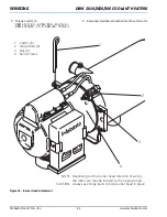
To prevent fires do not switch heater on
with burner swung open.
6.2
A
DJUSTMENTS
6.2.1
A
DJUSTMENT
OF
CO
2
C
ONTENTS
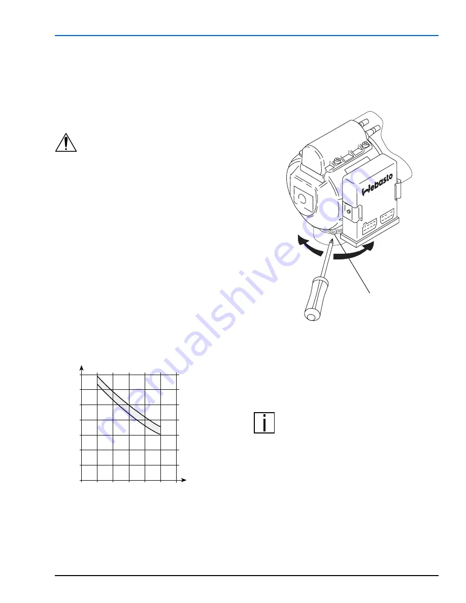
It is allowed to change the manufacturer’s setting for
combustion air quantity by rotation of the setting ring.
Measurement of the CO
2
value of the exhaust gas must
be performed followed by an adjustment of the
combustion air quantity as required in case of:
– repairs to the burner head
– irregularities in combustion
– functional checks
– nozzle replacement
6.2.1.1 S
ETTING
PROCEDURE
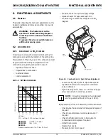
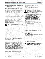
– Measure control unit power supply voltage
– Operate heater for approximately 5 min.
– Measure CO
2
contents and compare with CO
2
diagram
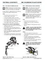
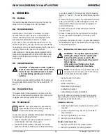
Figure 21:
Combustion Air / Fuel Mixture Adjustment
– Loosen locking screw (refer to Figure above) and
reposition shutter with locking screw until rated
value is obtained
– Tighten locking screw with 1.0 +0.5 Nm and apply
screw seal varnish to mark new position
NOTE:
CO
2
setting depends on fuel (viscosity)
and on geodetic altitude (0.1% per 100 m).
If proper setting cannot be obtained, proceed as follows:
– Check burner head air side for damage and replace if
required
– Check fuel pump pressure and replace pump if
required
– Check fuel filter and strainer in fuel pump for
contamination and replace if required
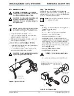
– Adjust fuel pressure
– Replace fuel nozzle
– Measure burner motor speed
DBW 20
1
0
(Nozzle: 0.35 gph)
DBW 2020
(Rev.
.33)
DBW 300
Fuel pump pressure set to 10 bar (145 psi)
CO
2
(V
o
l.
-%
)
18
20
22
24
26
28
30
6
7
8
9
10
11
12
13
9
10
11
12
13
14
15
Voltage
CO
2
- setting at 500 m above sea-level
+
–
CO
2
CO
2
Locking screw

