10
Tools required:
◆
Screws drivers
◆
Pliers
◆
Pipe wrench
◆
Wire cutters/crimpers
◆
Drill bit set
◆
Jigsaw
◆
Duct tape
◆
Electrical tape
◆
Teflon tape
◆
Compound Sealant for
thru hull fittings
◆
Hardware to secure
unit, pump, strainer,
grilles & control panel
The unit should be installed as low as possible, BUT NEVER IN THE BILGE OR
ENGINE ROOM AREAS, ENSURE THAT THE SELECTED LOCATION IS SEALED
FROM DIRECT ACCESS TO BILGE AND/OR ENGINE ROOM VAPORS. Installing
the unit as low as possible (such as under a V-berth, dinette seat or bottom of a
locker) and ducting the supply air as high as possible, creates an ideal airflow
condition. This type of installation will prevent short or premature cycling.
The unit should be positioned on a firm, level, horizontal surface and the
condensate drain line should run downward from the unit to a suitable drain
location. Plan all Connections, which must be made including ducting,
condensate drain, and seawater in and out, electrical power connections,
location of control, and seawater pump placement, to assure easy access for
routing and servicing.
4.5 Condensate Drains
The condensate drain pan is 2” (50mm) high with four drain locations. During
conditions of high humidity, condensate may be produced at a rate of
approximately 1/2 gallon per hour (1.9 liters per hour). Please pay more
attention, it is important to route condensate drains downward to a sump
pump. It is not recommended to route condensate drains to the bilge. After the
condensate drain installation is complete, test the installation by pouring water
into the pan and checking for good flow.
For installation of the condensate drain:
◆
Attach a 3/4" or 5/8” reinforced hose (as required) to the hose barb and secure with stainless steel hose clamps.
◆
Install the condensate drain hose downhill from the unit and aft to a sump.
◆
Up to 4 drain fittings may be used and the two hoses (teed) together using a tee fitting provided there is a
minimum 2" drop from the bottom of the base pan to the tee connection.
Summary of Contents for FCF 10
Page 2: ......
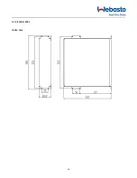
Page 16: ...16 4 13 2 20K 25K Units mm ...
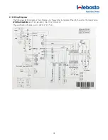
Page 19: ...19 WIRING DIAGRAM 12K 115V 12K 230V The specification of power cord is AWG12 3 3 2 5 ...
Page 20: ...20 WIRING DIAGRAM 16K 115V 16K 230V The specification of power cord is AWG12 3 3 2 5 ...
Page 30: ...30 NOTES ...
Page 31: ...31 NOTES ...


