13
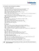
4.11 Electrical Connections, Grounding and Bonding
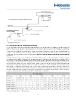
All A/C units have a terminal strip mounted inside the electric box. The terminal strip is labeled for proper connections
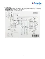
of the electrical supply, ground wires and pump circuits. A wiring diagram is provided in the electrical box and later in
this manual. The wiring diagram in the electrical box supersedes any found in this manual and ABYC standards. The
correct size circuit breaker should be used to protect the system as specified on the A/C unit's data plate label. A
minimum of 12 AWG boat cable should be used to supply power to the A/C unit and the seawater pump. All
connections shall be made with ring or fork terminals.
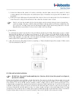
Turn off A/C power supply circuit breaker before opening
electric box.
Each A/C installed requires its own dedicated circuit breaker. If there is only one A/C installed, the seawater pump does
not require a circuit breaker; the wiring from the seawater pump is connected to the terminal strip in the electric box. If
two or more A/C use the same seawater pump, the pump wires will be connected to a pump relay, Please refer to the
wiring diagram. Electrical connections in the bilge and/or below the waterline should use heat shrink type butt splices.
Field wiring must comply with ABYC electrical codes. Power to the unit must be within the operating voltage range
indicated on the data plate. Properly sized fuses or HACR circuit breakers must be installed for circuit protection. See
table below for suggested circuit breaker size. All units must be effectively grounded to minimize the hazard of
electrical shock and personal injury. The following can be observed: AC (alternating current) grounding (green wire)
must be provided with the AC power conductors and connected to the ground terminal (marked "GRND") at the AC
power input terminal block of the unit(s), per ABYC standard E-8, or equivalent.
Fuse Information
BTU Capacity
6000
10000
12000
16000
24000
Voltage (V)
115 230
230
115
230
230
115
230
230
115
230
230
115 Soft
230
230
Frequency (Hz)
60
50
60
60
50
60
60
50
60
60
50
60
60
50
60
Starting Current (A)
45
25
54.5
25.5
26.5
39
41
46
Starting Time (ms)
150
125
340
140
190
320
250
350
Running Current (A)
11
5.6
12.4
6.2
8.4
20.4
8.6
12.5
*
Suggest Breaker (A) 15
10
10
15
10
10
20
15
15
**
25
20
20
30
25
25
*
Slow or Medium Delay
**
Slow Delay
Summary of Contents for FCF 10
Page 2: ......
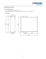
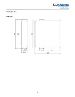
Page 16: ...16 4 13 2 20K 25K Units mm ...
Page 19: ...19 WIRING DIAGRAM 12K 115V 12K 230V The specification of power cord is AWG12 3 3 2 5 ...
Page 20: ...20 WIRING DIAGRAM 16K 115V 16K 230V The specification of power cord is AWG12 3 3 2 5 ...
Page 30: ...30 NOTES ...
Page 31: ...31 NOTES ...


