11 | Electrical Connections
27
11 Electrical Connections
WARNING
The size (gauge) of the wire must be suffi-
cient for the expected current flow. The
supplied wiring harness is sized for max-
imum length and must not be lengthened.
Failure to follow this direction can result in
fire.
WARNING
All wiring must be insulated against cuts
and abrasions. Failure to follow this instruc-
tion may result in fire, or inoperative com-
ponents.
WARNING
All electrical circuits must be protected with
fuses or automatic circuit breakers.
WARNING
Electrical cables and harnesses must be
routed and firmly secured in such a way as
to prevent against mechanical and thermal
stresses. Failure to follow this instruction
can result in a fire and / or the heater or its
components becoming inoperative.
Electrical components, such as relays, fuses,
switches, etc., must be installed so that they are pro-
tected. i.e. (water, high-pressure cleaners, etc.).
Check the data on nameplate to verify 12- or 24-
volt rating.
Disconnect the vehicle’s battery(ies) before in-
stalling the heater.
Make sure the electrical system is correctly
grounded.
Always comply with legal requirements.
CAUTION
All the cables and wires that are not re-
quired to be connected must be insulated
against accidental shorting or grounding.
11.1
Battery Connections
WARNING
All power connections must be fused within
14 in (356 mm) of the battery.
The heater’s power supply must be directly from the
vehicle’s batteries or main buss-bar. Power and
ground to the heater must be available after the
heater is switched OFF to ensure for proper cool-
down.
The heater control unit is equipped with low voltage
protection. It is imperative that the vehicle batteries
be kept in good condition for optimal heater opera-
tion.
1.
Route and secure the wire harness from the
Webasto heater to battery box.
2.
Strip and crimp the wires using the supplied ring
terminals to the positive (red) and negative
(brown) wire leads.
3.
Clean any corrosion from the battery terminals.
4.
Connect the leads to the battery terminals.
5.
Protect connections with an anti-corrosion com-
pound designed for use with electrical connec-
tions and battery terminals.
11.2
Switch and Timer
Connections
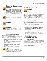
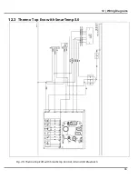
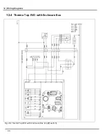
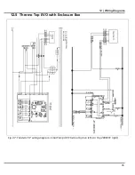
Install and connect the control element (SmarTemp
or rocker switch) per the instructions included with
the control element and the Wiring Diagrams.
The heater can be switched ON and OFF using the
following Webasto controls:
Summary of Contents for thermo top evo
Page 46: ...15 NOTES NOTES ...
Page 47: ......


