7 | Coolant System
15
7 Coolant System
WARNING
The vehicle’s cooling system is pressurized.
Allow the system to cool before working on
the cooling system. Failure to do so can
cause burns.
The cooling system must be bled carefully before us-
ing the heater for the first time or after the cooling
system has been serviced.
A properly bled cooling system can be identified by
the circulating pump operating virtually silent. Im-
proper bleeding may cause the heater to fault due to
an overheat condition. Refer to the workshop manual
for fault codes and diagnosis.
7.1
System Connections
The heater is connected to the vehicle’s cooling
system. The coolant quantity present must at least be
equal to the volume specified. See Coolant
Specifications in the Technical Data table on page 9.
Heater hoses used in this installation must at least
comply with SAE 20 R3 specifications. The hoses
must be routed without kinking and preferably uphill
from the heater to ensure proper bleeding.
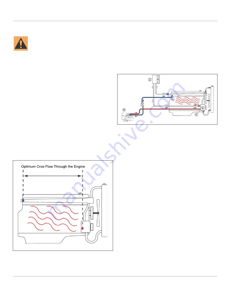
Fig. 10: Typical Pre-Heating System Configuration
Separate the heater supply and return connections
at the engine as far apart as is practical for optimum
engine heating and heater performance when the
heater is used for engine pre-conditioning.
1
Coolant Supply Con-
nection
2
Vehicle Heat Ex-
changer
5
Coolant Return Con-
nection
6
Engine Water Pump
3
Coolant Pump
7 Thermostat
4
Thermo Top EVO
7.2 Heater Connections
Refer to Fig. 11, the contact surfaces of the O-rings
in the heat exchanger must be clean. Apply a suit-
able lubricant to the O-rings prior to installation in
the heat exchanger.
Install the O-rings in place. Mount the coolant con-
nector housing in the retaining plate. Rotate the
connection pieces to the necessary installation posi-
tion. Fasten the retaining plate.
To enable the self-bleeding of the heater, the
coolant-outlet connection piece must be positioned
pointing 0° to 90° upward.
Fig. 9: Ensure Optimum Cross-Flow
Summary of Contents for thermo top evo
Page 46: ...15 NOTES NOTES ...
Page 47: ......


