16
7 | Coolant System
NOTE
IMPORTANT
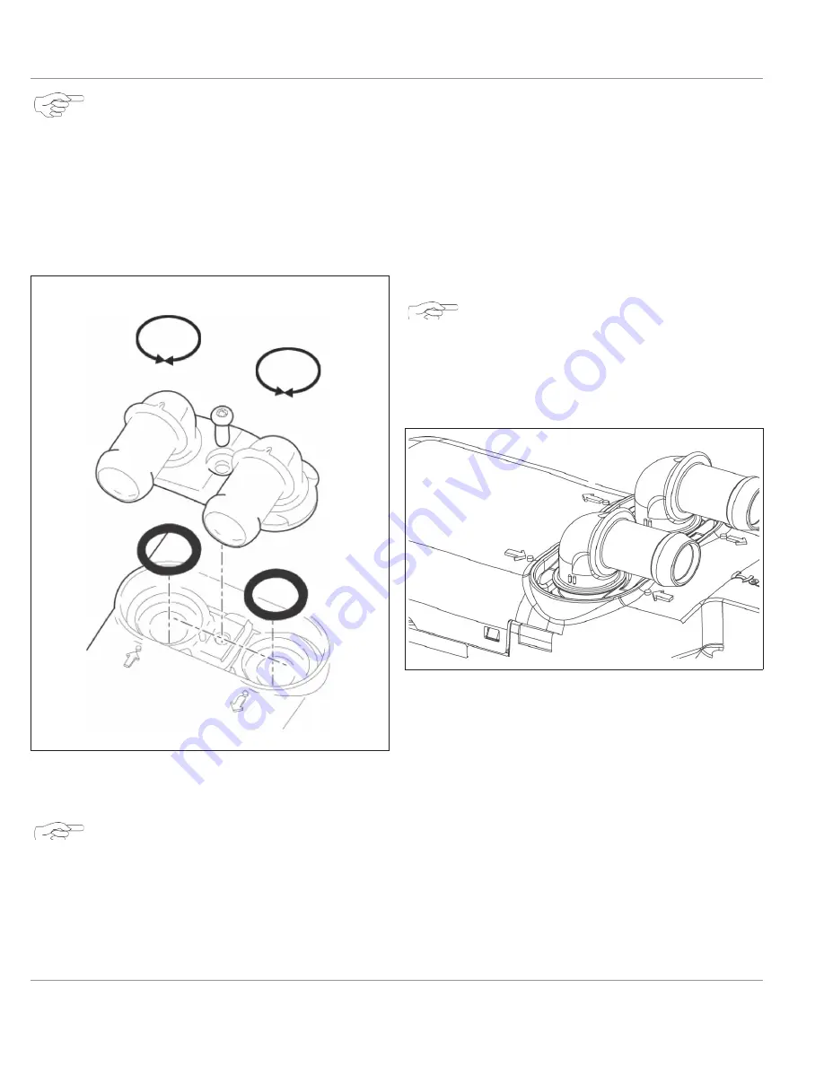
The heater comes pre-assembled; however,
if direction of the water inlet or outlet
needs to changed use the following torque
specification.
5X15mm self-tapping screw, torque to 5 lb-
ft (7 Nm).
Fig. 11: Coolant Connections at Heater
7.3
Coolant System Connections
NOTE
The hose clamps must be tightened with a
torque of 40 lb. in. (4.5 Nm). The use of sil-
icone hose requires special hose clamps.
The coolant quantity in the coolant circuit corres-
ponds to the minimum volume specified in Technical
The heater should preferably be integrated into the
coolant system close to the inlet of the vehicle heat
exchanger.
Connect the heater to the vehicle coolant system as
shown in Coolant System on page 15.
Route coolant hoses in such a way to avoid kinks
and pinches. Be sure the hoses run slightly uphill
from the heater to help in bleeding the coolant sys-
tem.
Secure hose connections using hose clamps.
NOTE
When integrating the coolant hoses in the
coolant circuit, the correct direction of flow
of the coolant must be ensured. Use the
coolant flow arrows on the heater when in-
stalling coolant hoses.
Fig. 12: Flow Direction Arrows
Care must be taken to bleed the cooling system be-
fore the heater is started for the first time or after re-
filling with fresh coolant. Heater and lines should be
installed in such a way as to ensure static bleeding.
Insufficiently bleeding the coolant circuit can lead to a
malfunction due to overheating or to frequent switch-
on/switch-off cycles of the heater.
Separate the heater supply and return connections
at the engine as far apart as possible for optimum
engine heating and heater performance.
Summary of Contents for thermo top evo
Page 46: ...15 NOTES NOTES ...
Page 47: ......


