24
9 | Combustion Air System
9
Combustion Air System
9.1
General
Under no circumstances may the combustion air be
taken from areas occupied by people. The combus-
tion air intake opening must not point in the direc-
tion of travel. It must be located so that it cannot
become clogged with dirt or snow and cannot suck
in splashing water.
NOTE
The combustion air must be extracted using
a combustion air tube from a position that
is as cool as possible and protected from
splashing water.
NOTE
If the combustion air intake tube cannot be
installed so that it slopes downwards, a wa-
ter drain hole with a diameter of 5/32 in (4
mm) is to be made at its lowest point.
There is no pressure difference (positive or negat-
ive) between the exhaust gas outlet and the com-
bustion air inlet.
Combustion air is not extracted from enclosed
areas used by people.
The combustion air intake must route in such a
way that the intake will not terminate in the vi-
cinity of the heater’s or vehicle’s exhaust pipe.
The combustion air intake opening has the fol-
lowing requirements:
–
It must be positioned in a cool place above
the maximum permissible fording level of the
vehicle, in a location protected from spray.
–
It must not be possible for it to become
clogged with dirt.
–
It must not be possible for it to draw in ex-
haust gases.
–
The combustion air intake opening does not
face in the direction of travel.
When installing the heater in the same compart-
ment as the vehicle’s fuel tank:
–
Combustion air must be drawn in from out-
side.
–
Exhaust gas must be routed to the outside.
–
Through holes must be splash-proof.
9.2
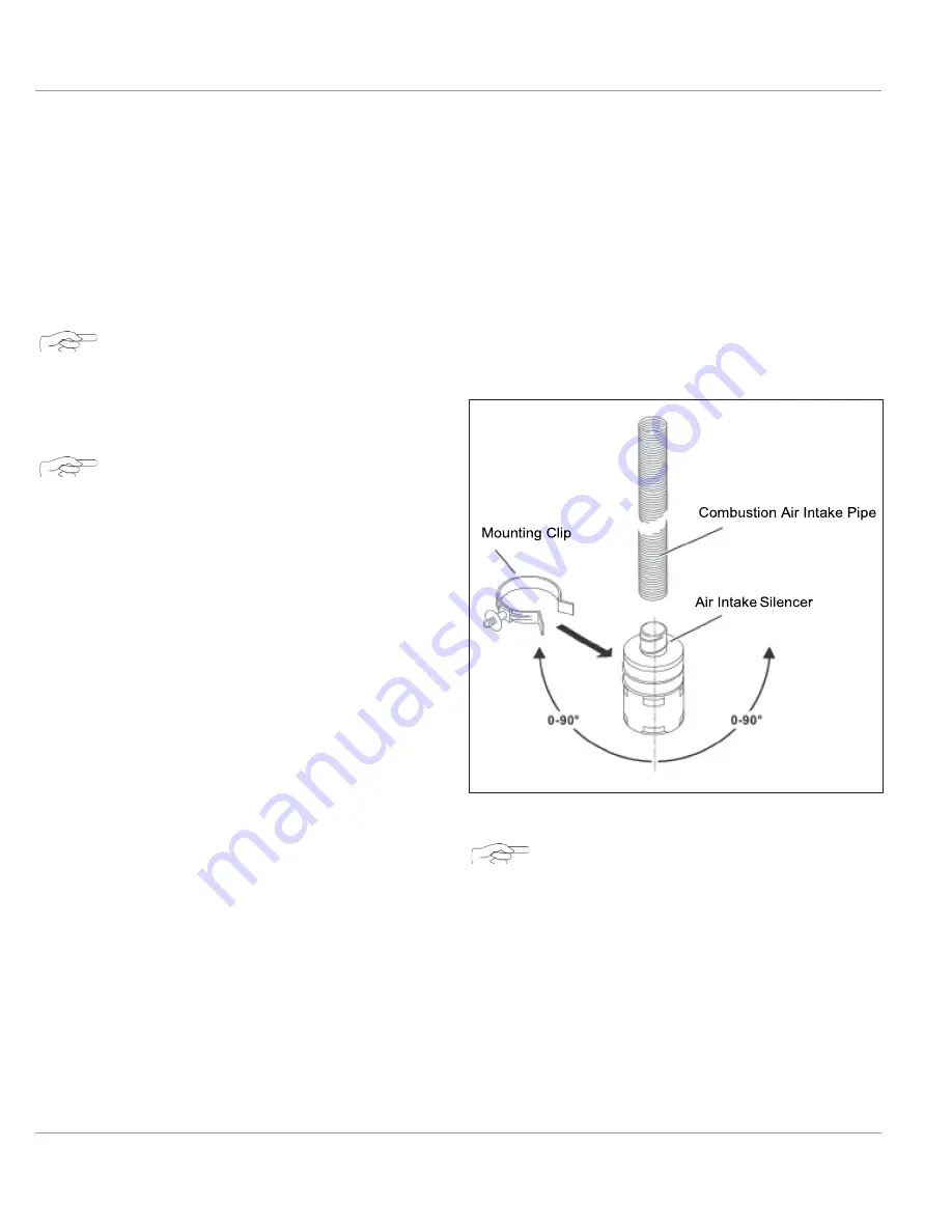
Combustion Air Silencer
(Optional)
Fig. 23: Optional Air Intake Assembly
NOTE
Screw a combustion-air intake pipe with a
maximum length of 3 ft. (1M) onto the
combustion-air intake connection piece of
the heater. Screw the combustion-air intake
silencer as far as possible into the combus-
tion-air intake pipe.
(Optional)
Summary of Contents for thermo top evo
Page 46: ...15 NOTES NOTES ...
Page 47: ......


