ASSEMBLY INSTRUCTIONS - LF43SPBR 17" Roller model
Remove the machine and all components from the carton. Assemble as follows:
1a.
Select the left hand
the two studs on the
right hand side of the
mower,
ensure that the
U shape of the handle
goes towards the
chassis
.
2.
Select the right hand
the two studs on the left
hand side of the mower,
ensure that the U shape of the handle
goes towards the
chassis. Fix with two
cap head nuts.
4.
wire recoil rope guide
to the right hand clamp
bolt, this goes on the
inside of the handle
between the handle
and the securing nut.
6. Fit the Operator
Presence Cable,
remove the lever from
its mounting by easing it
from the handle, attach
the Z cable end to the
OPC lever as shown in
lever to the handle.
8. Ensure you have
attached the correct
cable to the correct
lever.
8)
3.
Assemble the upper
handle to the lower
handle using the two
clamp bolts and nuts,
ensuring that the large
washer goes against the
clamp handle on the
outside of the handle
as per the photo.
5.
Tension clamp bolts
to ensure the handles
7. Fit the Self Propelled
drive cable, again
remove the lever from
its mounting by gen-
tly easing it from the
handle, attach the Z
cable end to the Self
Propelled drive lever as
the lever to the handle.
9. Fit the cable router
to the handle using the
securing bolt supplied,
the inside of the handle
as per the photo.
10. Hold in the
Operator control handle
and pull on the recoil
starter rope so you can
attach it through the
wire recoil rope guide.
1b.
Fix with two cap
head nuts.
11
.
Set the grass bag
and grass bag frame
together then lock the
plastic buckles on the
grass bag frame.
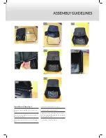
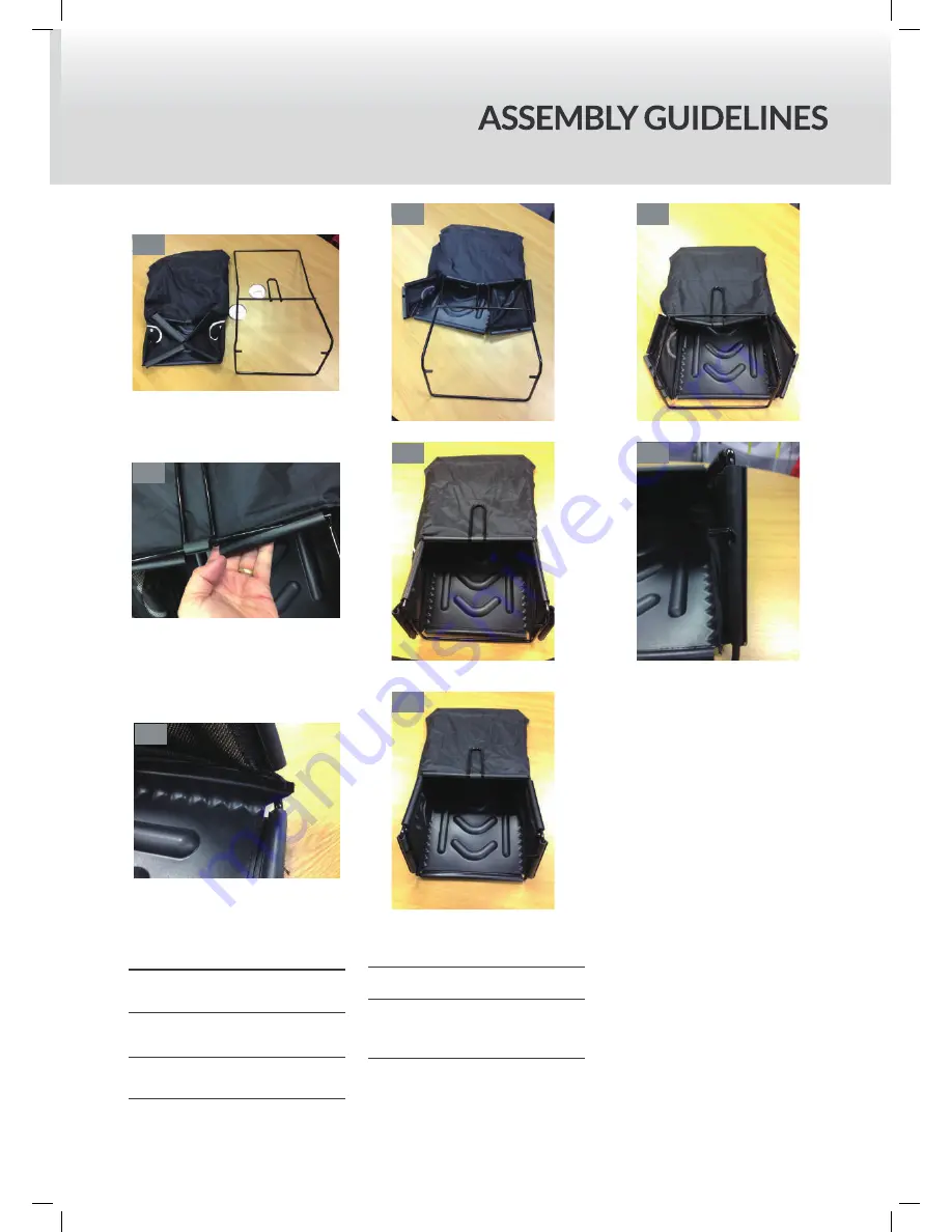
Grass collector & Frame (fig. 1)
Place the Frame into the Grass Collector
(fig. 2).
Ensure the carry handle remains outside of
the Collector (fig. 3).
Start attaching the Collector to the Frame
(fig. 4).
Attach the top sections first (fig. 5).
Attach the side sections (fig. 6).
Ensure the Grass Collector sides sit inside
the Frame when attaching the lower section
of the Collector (fig. 7).
The finished Collector (fig. 8).
fig. 1
fig. 2
fig. 3
fig. 4
fig. 5
fig. 6
fig. 7
fig. 8
INSTRUCTION MANUAL
ASSEMBLY INSTRUCTIONS - LF43SPBR 17" Roller model
Remove the machine and all components from the carton. Assemble as follows:
1a.
Select the left hand
the two studs on the
right hand side of the
mower,
ensure that the
U shape of the handle
goes towards the
chassis
.
2.
Select the right hand
the two studs on the left
hand side of the mower,
ensure that the U shape of the handle
goes towards the
chassis. Fix with two
cap head nuts.
4.
wire recoil rope guide
to the right hand clamp
bolt, this goes on the
inside of the handle
between the handle
and the securing nut.
6. Fit the Operator
Presence Cable,
remove the lever from
its mounting by easing it
from the handle, attach
the Z cable end to the
OPC lever as shown in
lever to the handle.
8. Ensure you have
attached the correct
cable to the correct
lever.
8)
3.
Assemble the upper
handle to the lower
handle using the two
clamp bolts and nuts,
ensuring that the large
washer goes against the
clamp handle on the
outside of the handle
as per the photo.
5.
Tension clamp bolts
to ensure the handles
7. Fit the Self Propelled
drive cable, again
remove the lever from
its mounting by gen-
tly easing it from the
handle, attach the Z
cable end to the Self
Propelled drive lever as
the lever to the handle.
9. Fit the cable router
to the handle using the
securing bolt supplied,
the inside of the handle
as per the photo.
10. Hold in the
Operator control handle
and pull on the recoil
starter rope so you can
attach it through the
wire recoil rope guide.
1b.
Fix with two cap
head nuts.
11
.
Set the grass bag
and grass bag frame
together then lock the
plastic buckles on the
grass bag frame.
Select the left hand lower handle and fix to
the two studs on the right hand side of the
mower, ensure that the U shape of the
handle goes towards the chassis (fig. 1a).
Fix with two cap head nuts (fig. 1b).
Select the right hand lower handle and fix to
the two studs on the left hand side of the
mower, ensure that the U shape of the
handle goes towards the chassis.
Fix with two cap head nuts (fig. 2).
Assemble the upper handle to the lower
handle using the two clamp bolts and nuts,
ensuring that the large washer goes against
the clamp handle on the outside of the
handle as per the photo (fig 3).
Place the wire recoil rope guide to the right
hand clamp bolt, this goes on the inside of
the handle between the handle and the
securing nut (fig. 4).
Tension the clamp bolts to ensure the
handles firmly lock together (fig. 5).
Fit the Operator Presence Cable, remove
the lever from its mounting by easing it from
the handle, attach the Z cable end to the
OPC lever as shown in lever to the handle
(fig. 6).
Fit the Self Propelled drive cable, a(RR17SP
Only) gain remove the lever from its
mounting by gently easing it from the
handle, attach the Z cable end to the Self
Propelled drive lever & refit the lever to the
handle (fig . 7).
Ensure you have attached the correct cable
to the correct lever (fig. 8).
Fit the cable router to the handle using the
securing bolt supplied, this should be fitted
to the inside of the handle (fig. 9).
Hold in the Operator control handle and
pull on the recoil starter rope so you can
attach it through the wire recoil rope guide
(fig. 10).
ASSEMBLY INSTRUCTIONS - LF43SPBR 17" Roller model
Remove the machine and all components from the carton. Assemble as follows:
1a.
Select the left hand
the two studs on the
right hand side of the
mower,
ensure that the
U shape of the handle
goes towards the
chassis
.
2.
Select the right hand
the two studs on the left
hand side of the mower,
ensure that the U shape of the handle
goes towards the
chassis. Fix with two
cap head nuts.
4.
wire recoil rope guide
to the right hand clamp
bolt, this goes on the
inside of the handle
between the handle
and the securing nut.
6. Fit the Operator
Presence Cable,
remove the lever from
its mounting by easing it
from the handle, attach
the Z cable end to the
OPC lever as shown in
lever to the handle.
8. Ensure you have
attached the correct
cable to the correct
lever.
8)
3.
Assemble the upper
handle to the lower
handle using the two
clamp bolts and nuts,
ensuring that the large
washer goes against the
clamp handle on the
outside of the handle
as per the photo.
5.
Tension clamp bolts
to ensure the handles
7. Fit the Self Propelled
drive cable, again
remove the lever from
its mounting by gen-
tly easing it from the
handle, attach the Z
cable end to the Self
Propelled drive lever as
the lever to the handle.
9. Fit the cable router
to the handle using the
securing bolt supplied,
the inside of the handle
as per the photo.
10. Hold in the
Operator control handle
and pull on the recoil
starter rope so you can
attach it through the
wire recoil rope guide.
1b.
Fix with two cap
head nuts.
11
.
Set the grass bag
and grass bag frame
together then lock the
plastic buckles on the
grass bag frame.
fig. 1b
fig. 2
fig. 1a
fig. 3
fig. 4
fig. 5
fig. 6
fig. 7
fig. 8
fig. 9
fig. 10
INSTRUCTION MANUAL
INSTRUCTION MANUAL
Summary of Contents for WERR17P
Page 2: ......
Page 17: ...NOTES...
Page 18: ...WERR17P 193865002...
Page 20: ...WERR17SP 193806004...
Page 21: ......
Page 28: ...Webb Lawnmowers Murdock Road Dorcan Swindon Wiltshire SN3 5HY...


