background image

27

CR4

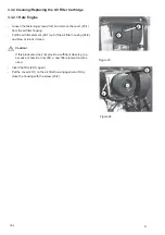
3.3.2 Cleaning/Replacing the Air Filter Cartridge

3.3.2.1 Hatz Engine

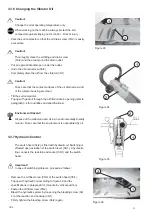
- Loosen the fastening screw (23/2) and remove the cover (23/1)

from the air filter housing.

- Pull the air filter element (24/1) out of the air filter housing (24/2)

and blow or knock it clean.

Caution!

If this procedure does not provide a sufficient cleaning (e. g.
because of humid or oily dirt), a new filter element must be
used.

- Insert the filter (24/1) again.
- Put the cover (23/1) on the air filter housing again and firmly

close the housing with the screw (23/2).

1

2

Figure 23

Figure 24

1

2

Summary of Contents for CR 4

Page 1: ...AINTENANCE INSTRUCTIONS Weber Maschinentechnik GmbH P O Box 21 53 D 57329 Bad Laasphe Rückershausen Phone 27 54 398 0 Telefax 27 54 3 98 101 Switchboard 3 98 102 Spare Parts CR 4 Hatz 1 B 30 Honda GX 270 0506 englisch ...

Page 2: ...2 CR4 ...

Page 3: ...r an extended storage e g during the winter season We placed a great emphasis on a user friendly lay out with clear pictorial and textual information In the text you will find figures in brackets which point out to illustrations whereby the first figure indicates the figure number and the second one separated by a dash indicates the item number on the corresponding illustration Example 1 2 1 means...

Page 4: ...individual countries of use must be followed The soil compactor has been exclusively designed for the compaction of sand gravel crushed stone semi cohesive mixed aggregates concrete block pavement Any other use of the soil compactor is considered contrary to its designated use The owner of the soil compactor bears the sole responsibility for any misuse of the machine Driving Permission Only trustw...

Page 5: ...Operation 20 2 7 1 Stopping Hatz Engine 21 2 7 1 1 Stopping Honda Engine 21 3 Maintenance 22 3 1 Safety Precautions for Maintenance Work 22 3 2 Maintenance Survey 23 3 2 1 Maintenance 23 3 3 Description of the Maintenance Work 24 3 3 1 Changing the Engine Oil Hatz Engine 24 3 3 1 1 Cleaning the Engine Oil Filter Hatz Engine 25 3 3 1 2 Changing Adding Engine Oil Honda Engine 26 3 3 2 Cleaning Repla...

Page 6: ...4 1 1 Illustration 1 2 3 6 7 8 9 10 12 5 11 4 1 Engine 2 Drive lever 3 Handle 4 Lifting lug 5 Reversible starter 6 Base plate 7 Protection frame 8 Engine bracket 9 Vibrator 10 V belt guard 11 Spring bar 12 Speed adjusting lever 13 Vulkollan plate not shown ...

Page 7: ...s screwed down to the base plate 1 6 and sets it vibrating The vibrating base plate performs the vibration work and travelling motion Accessories A damper plate 2 4 3 and an undercarriage 2 4 4 are available as optional extras Operation The soil compactor is started by means of a reversible starter 1 5 The machine is steered with the handle 1 3 holding the lever 1 12 for the engine speed adjustmen...

Page 8: ...Hatz Type 1 B 30 1 B 30 Max output according to DIN 70020 in kW HP 5 6 7 6 at 3600 5 6 7 6 at 3600 Type of combustion 4 stroke Diesel 4 stroke Diesel Operating speed 3000 3000 Driving speed depending on soil conditions in m min 22 22 Gradeability depending on soil conditions in 30 30 Depth compaction in cm 40 40 Performance in m h 660 858 Vibration System Two shaft vibrator Two shaft vibrator Mode...

Page 9: ... Honda Type GX 270 GX 270 Max output according to DIN 70020 in kW HP 6 6 9 0 at 3600 6 6 9 0 at 3600 Type of combustion 4 stroke gasoline 4 stroke gasoline Operating speed 3000 3000 Driving speed depending on soil conditions in m min 22 22 Gradeability depending on soil conditions in 30 30 Depth compaction in cm 40 40 Performance in m2 h 660 858 Vibration System Two shaft vibrator Two shaft vibrat...

Page 10: ...lace according to 2000 14 EG in dB A 101 99 Sound power level LWA according to I2000 14 EG in dB A 108 108 Hand arm vibration weighted root mean square acceleration at the handle determined according to 2002 44 EG Part 1 in m s 5 10 5 10 The indicated noise and vibration data were determined with the engine at nominal speed and the vibration system turned on 2000 14 EG During operation these data ...

Page 11: ...t always have a sufficient visibility on the soil compactor s zone of operation The operator must be assisted by a second person if because of the operating conditions the visibility on the zone of operation is restricted Stability Soil compactors must be used and operated in a way ensuring their stability The machine s stability is especially endangered on slopes and brinks Thus keep clear of slo...

Page 12: ...he machine may overturn Put the crane hook 2a 1 into the protection frame 2a 2 Danger Only use a lifting tackle and a crane of a sufficient bearing capacity Danger Do not enter the zone under the suspended load 2 2 Transport 2 2 1 Loading by Crane 2 3 Commissioning Figure 2 1 2 Figure 2 a 1 2 Short distances on the job site can be covered by the soil compactor in accordance with paragraph 2 6 For ...

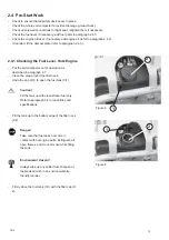
Page 13: ...he tank Environment Hazard Always wipe up any spilled fuel Dispose of fuel soaked cloth in an environmentally friendly manner Firmly close the fuel tank 3 1 with the filler cap 3 2 2 4 Pre Start Work 2 4 1 Checking the Fuel Level Hatz Engine Figure 3 1 Figure 4 1 2 2 Check to ensure that all safety devices are in place Check the whole soil compactor for evident damage visual check Check all screwe...

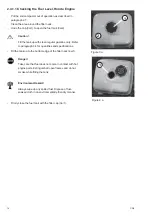
Page 14: ...only Refer to paragraph 3 4 for quantities and specifications Fill the tank up to the bottom edge of the filler neck 4a 1 Danger Take care that fuel does not come in contact with hot engine parts Extinguish all open flames and do not smoke while filling the tank Environment Hazard Always wipe up any spilled fuel Dispose of fuel soaked cloth in an environmentally friendly manner Firmly close the fu...

Page 15: ...ifications Firmly screw the oil dipstick down Caution The engine oil level must be checked with the soil compactor standing horizontally on the ground Pull out the oil filler screw with the oil dipstick 5a 1 wipe it off with a clean non fluffing cloth and insert it again Caution Do not screw down Pull the oil dipstick out once again Caution The oil level must reach up to the top mark 5b max If req...

Page 16: ... 4 asshown Align the Vulkollan plate 6a 1 beneath the base plate 6a 4 in the long holes located at the front of the Vulkollan plate Fasten the Vulkollan plate 6a 3 with the holder 6a 1 and the screws 6a 2 at the font beneath the base plate 6a 4 Fasten the Vulkollan plate 6b 1 with the holder 6b 2 and the screws 6b 3 at the back Figure 6 Figure 6a Figure 6b Important Check to ensure that the Vulkol...

Page 17: ...h the base plate 6e 4 by means of the drawbar 6e 3 The locking pin 6f 1 must sit in the iron clip 6f 2 of the undercarriage Towthesoilcompactorintothedesireddirectionby means of the handle 6e 3 Warning Check to ensure that the locking pin 6f 1 correctly engages in the iron clip 6f 2 If the locking pin is incorrectly fitted the soil compactor may disengage from the undercarriage Risk of injury beca...

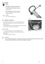
Page 18: ...7 1 into the full speed position Slowly pull the handle 8 1 of the reversible starter 8 2 until a resistance is felt Let the handle 8 1 recoil into its original position and then firmly pull the cable with both hands to start the engine Important If the engine fails to start repeat the starting procedure As soon as the engine starts let the starter cable return into its housing 8 2 Let the engine ...

Page 19: ...ke to the right Slowly pull the handle 11 1 of the reversible starter 11 2 until a resistance is felt Let the handle 11 1 recoil into its original position and then firmly pull the cable with both hands to start the engine Important If the engine should fail to start repeat the starting procedure As soon as the engine starts let the starter cable recoil into its housing 11 2 Slowly bring the choke...

Page 20: ...ip out of control Warning During work breaks even if they are short the soil compactor must be put out of operation refer to 2 7 Steer the soil compactor with the handle 12 1 into the desired direction 2 7 Putting the Soil Compactor Out of Operation Before work breaks and at the end of every day s shift the soil compactor must be parked on a stable base which should be as horizontal as possible Wa...

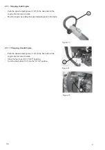
Page 21: ...e engine idle for some minutes Stop the engine by pulling the speed adjusting lever to the back 2 7 1 1 Stopping Honda Engine Push the speed adjusting lever 12 1 to the back and let the engine idle for some minutes Close the fuel cock 14 1 OFF position Turn the stop button 15 1 into the STOP position Figure 14 Figure 15 ...

Page 22: ...nd disposed off according to the relevant environmental protection regulations Prior to any work on parts which are not protected the engine must be secured against unintentional starting After completion of service work all protective devices must be properly installed again Modifications and Retrofittings For safety reasons any modifications and retrofittings made on the soil compactor without t...

Page 23: ...the air filter element check it for damage and replace it if required 3 3 2 Engine Check the engine oil level 2 4 2 Every 50 operating hours Honda engine Change the engine oil Clean the spark plug Every 150 operating hours Whole machine Check all screwed connections for tight seat retighten them if necessary All bare parts Slightly oil Diesel engine Change the engine oil 3 3 1 Replace the oil filt...

Page 24: ...il soaked cloth in an environmentally friendly manner Danger Danger of scalding because of hot oil Undo the oil filler screw dipstick 16 1 Undo the protective cap 16 2 Screw the oil drain hose 17 1 onto the drain valve 17 2 and completely drain the engine oil Important Screwing the drain hose down opens the drain valve oil escapes Undo the oil drain hose 17 1 Put the protective cap 16 2 onto the d...

Page 25: ... inside towards the outside Check the packing ring 19 2 for damage and tight seat if damaged replace the oil filter Slightly oil the packing rings 19 2 on both sides of the oil filter Completely push the oil filter 19 1 into the crankcase housing Caution Take care that both 1 ends of the tension springs 20 1 are correctly fitted to the oil filter before fastening the screws Top up with engine oil ...

Page 26: ...ns Wipe up any oil residues and dispose of the oil soaked cloth in an environmentally friendly manner Important Screwing the oil drain hose down opens the drain valve oil escapes Danger Danger of scalding because of hot oil Undo the oil filler screw dipstick 21 1 Unscrew the protective cap of the oil drain valve 21 2 Screw the oil drain hose 22 1 down to the drain valve 22 2 and completely drain t...

Page 27: ...ir filter element 24 1 out of the air filter housing 24 2 and blow or knock it clean Caution If this procedure does not provide a sufficient cleaning e g because of humid or oily dirt a new filter element must be used Insert the filter 24 1 again Put the cover 23 1 on the air filter housing again and firmly close the housing with the screw 23 2 1 2 Figure 23 Figure 24 1 2 ...

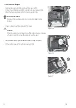
Page 28: ... Hazard Dispose of the washing solution in an environmentally friendly manner Knock or blow the air filter element 26 1 clean Caution If this procedure does not provide a sufficient cleaning e g because of humid or oily dirt a new filter element must be used Insert the filter 27 1 again and fasten it with the wing nut 27 2 Fit the air filter cover 25 1 with the wing nut 25 2 Figure 26 Figure 25 Fi...

Page 29: ...ctor out of operation as described in paragraph 2 7 Pull the fuel line 28 1 from the fuel filter 28 2 and fit the new filter Environment Hazard Immediately wipe up any escaping fuel dispose of the fuel soaked cloth in an environmentally friendly manner 1 Figure 28 Figure 29 1 2 ...

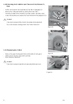
Page 30: ...excessive wear replace the V belt as described in paragaph 3 3 5 Caution Take care to properly fit the V belt on the pulleys belt alignment Due to the special centrifugal clutch the V belt is tensioned 3 3 5 Replacing the V Belt Remove the upper V belt guard 30 2 and the bottom V belt guard 30 3 by loosening the screws 30 1 and 30 4 Put on the new V belt 32 1 Caution Take care to properly align th...

Page 31: ...n opening refer to paragraph 3 4 for quantities and specifications Environment Hazard Dispose of the collected used oil in an environmentally friendly manner Take care that the environment is not polluted by oil 3 3 7 Hydraulic Control The switch head 34 2 is filled with hydraulic oil Switching is effected upon actuation of the switch lever 34 1 A hydraulic line connects the reaction end socket 36...

Page 32: ...ibrator Initial filling Fuchs Titan 5 Speed 1 0 l 1 0 l SL 75 W 90 Hydraulic control Fully synthetic gear oil DEXRON II D ATF Initial filling as required as required Fuchs TITAN ATF 3000 or equivalent Greasing points High pressure grease lithium saponified as required as required acc to DIN 51825 KPF2 API GL 5 GL 4 Diesel Diesel acc to DIN 51601 DK or BS2869 A1 A2 or STM D975 1D 2D Regular gasolin...

Page 33: ... given in the column Remarks of the maintenance survey chart paragraph 3 and trouble shooting chart paragraph 4 2 allow a quick failure elimination on condition that the given order is precisely kept to when service work is carried out Any service work has to be made with appropriate tools and in accordance with the safety regulations set out in this operating and maintenance manual If a problem p...

Page 34: ...s described 2 5 Lack of fuel Check the fuel level 2 4 1 Dirty fuel filter Replace the fuel filter 3 3 3 Dirty air filter Clean replace the air filter cartridge 3 3 2 No vibration no or insufficient forward travel Defective vibrator V belt Replace the vibrator V belt 3 3 5 Delayed control Air in the hydraulic switching system Bleed the switching system 3 3 7 ...

Page 35: ...ompactor is to be stored for more than 6 months additional measures must be taken in accordance with your WEBER service Assembly Group Measure Remarks Whole soil compactor Thoroughly clean Check condition fastenings and tightness Have any failures ascertained repaired All bare parts Apply a slight film of grease or oil Fuel tank Add fuel up to the bottom edge of the filler neck 2 4 1 Engine Check ...

Page 36: ...36 CR4 ...

Page 37: ...37 CR4 ...

Page 38: ......

Page 39: ...9 info webermt nl in France WEBER Technologie SARL 26 rue d Arsonval 69680 Chassieu Telefon Telefax E Mail 33 0 472 791020 33 0 472 791021 france webermt com in Poland WEBER Maschinentechnik Sp zo o Ul Grodziska 7 05 830 Stara Wies Telefon Telefax E Mail 48 0 22 739 70 80 48 0 22 739 70 81 48 0 22 739 70 82 info webermt com pl in USA and Canada WEBER Machine USA Inc 40 Johnson Ave 112 Bangor ME 04...

Page 40: ...ory Rollers Joint Cutters Internal Vibrators and Converters Vibrating Motors Stone Saws Rotary Trowels and many other Weber MASCHINENTECHNIK GmbH Im Boden D 57334 Bad Laasphe Rückershausen P O Box 2153 D 57329 Bad Laasphe Phone 27 54 398 0 Telefax 27 54 398 101 ...

Reviews: