background image

14 

CR 3-II E

1

2

3

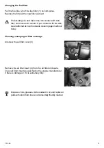
Adjusting the guide bar

Adjust the desired work height of the guide bar with 

the set screw (1).

Checking the engine oil level

Pull the oil dip stick out of the crankcase.

min max

The correct oil level is between the min. and max. marks.

Stop operating the engine immediately when the oil level 

reaches the min. mark and top up oil until it reaches the 

max. mark. Risk of engine damage if the oil level drops 

below the minimum oil level in unfavorable operating 

conditions.

Checking the fuel level

Open the cover (2), unscrew and remove the gas cap (3), 

check the fill level, and if necessary, top up with clean diesel 

fuel to the lower edge of the filler neck.

For work at the fuel system, have a suitable fire-

extinguishing agent ready.

Fire, naked light, and smoking is forbidden!

Summary of Contents for CR 3-II E

Page 1: ...lisch bersetzung der Original Betriebsanleitung Operating and Maintenance Manual Weber Maschinentechnik GmbH Im Boden 5 8 10 D 57334 Bad Laasphe R ckershausen Germany Tel 49 0 27 54 398 0 Fax 49 0 27...

Page 2: ...2 CR 3 II E...

Page 3: ...n 8 Device description 9 Technical data 10 Activities prior to starting work 12 Starting 15 Compacting 16 Shutting down 16 Maintenance overview 17 Maintenance work 18 Operating fluids and fill levels...

Page 4: ...ease the reliability and service life of your soil compactor This operating and maintenance manual must always be available at the implementation site of the soil compactor If necessary you can obtain...

Page 5: ...or which the owner shall be exclusively responsible All liability is rejected if damage occurs due to non compliance with this provision This risk is borne solely by the user Easily foreseeable misuse...

Page 6: ...eas or in areas that are poorly ventilated tunnels caves covered pits etc Be particularly cautious when operating the engine in the vicinity of people and livestock Maintenance and repair work Only us...

Page 7: ...year The results of the inspection must be recorded in writing and must be stored at least until the next inspection Cleaning work Prior to cleaning the compactor with a high pressure cleaner protect...

Page 8: ...8 9 10 Graphic presentation Overall view CR 3 II E 1 Engine 2 Drive lever 3 Guide bar 4 Lifting ring 5 Base plate 6 Protective frame 7 Exciter 8 Gas lever 9 Attachment plates 10 Battery box battery 11...

Page 9: ...orce is transferred to the exciter mechanically via a V belt Operation Start the Hatz diesel engine via the electrical start device After starting vibration is switched on via the centrifugal clutch a...

Page 10: ...in m min 22 Incline capacity ground dependent in 35 Area capacity with attachment plates in m h 585 702 819 Vibration System Two wave vibrator Drive concept Mechanical Frequency in Hz 80 Centrifugal f...

Page 11: ...CR 3 II E 11 2 1 3 4 5 6 1 Description 2 TYPE 3 Serial number 4 Year of construction 5 Mass 6 Rated power kW...

Page 12: ...rane hook into the lifting ring 3 and lift the machine onto the desired means of transport Only use lifting machines with a minimum bearing capacity of 300 kg Do not step under suspended loads Transpo...

Page 13: ...epeat the procedure for the second side Set the machine on the undercarriage Bring the guide bar into movement position and arrest it with the movement safeguard 1 Pay attention to the tire pressure o...

Page 14: ...hen the oil level reaches the min mark and top up oil until it reaches the max mark Risk of engine damage if the oil level drops below the minimum oil level in unfavorable operating conditions Checkin...

Page 15: ...ive mat rests under the base plate Starting Bring the gas lever into full throttle position Insert the ignition key 3 and turn to position 1 Turn the ignition key 3 to position 2 Release the ignition...

Page 16: ...g down Bring the gas lever 3 into idle position The engine can only be switched off via the switch off button Press the switch off button 4 until the engine comes to a standstill Turn the ignition key...

Page 17: ...th skin they can cause skin cancer Upon contact with the skin clean affected skin with suitable cleaning agent without delay If accessible during maintenance check the condition and stability of all s...

Page 18: ...en at operating temperature When working in the area of the engine compartment there is danger of being burned Risk of scalding due to hot oil Maintenance work Changing the engine oil Open the screw c...

Page 19: ...it is extremely dirty Changing the fuel filter Pull the fuel line 2 off the fuel filter 1 on both sides Replace the filter with a new filter element Dispose of oils greases cloths soaked in oil and re...

Page 20: ...large enough to prevent oil from spilling onto the ground Dispose of waste oil in an environmentally friendly manner regulation on waste oils Wipe up off oil slick and oil residue and dispose of fuel...

Page 21: ...CE CF CG or SHPD or CCMC D4 D5 PD2 0 9 l Fuel tank Diesel Diesel in accordance with DIN 51601 DK or BS2869 A1 A2 or STM D975 1D 2D 3 0 l Vibrator Fully synthetic transmission fluid API GL 5 GL 4 Firs...

Page 22: ...e start process as prescribed Check the fuel level Change the fuel filter Clean change air filter cartridge No vibration no forward motion or insufficient forward motion Vibrator V belt defective Chan...

Page 23: ...5 Temperature switch on the cylinder head 4 Oil pressure switch 3 Starter terminal 50 2 For flywheel alternator Terminal L on the regulator 1 Generator B 0 Mass X1 Terminal strip on the valve box S7 O...

Page 24: ...ark Check air filter clean replace if necessary Check fuel filter change if necessary All bare parts gas lever accelerator control cables fastening bolts Oil grease Starter battery if there is one Rem...

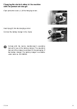
Page 25: ...ging socket Insert plug 2 into the charging socket Connect the battery charger to the mains Comply with the device manufacturer s operating manual for use of the battery charger The operating manual o...

Page 26: ...26 CR 3 II E...

Page 27: ...ARL 14 rue d Arsonval 69680 Chassieu Telephone Fax E mail 33 0 472 791020 33 0 472 791021 france webermt com in Poland WEBER Maschinentechnik Sp zo o Ul Jeziorki 86 02 863 Warszawa Telephone Fax E mai...

Page 28: ...ration plates Vibrating tampers Vibration rollers Joint cutters Internal vibrators and converters Weber MASCHINENTECHNIK GmbH Im Boden 57334 Bad Laasphe R ckershausen Telephone 49 0 27 54 398 0 Fax 49...

Reviews:

Related manuals for CR 3-II E