background image

29

CR7

4.2  Trouble Shooting

Failure

Possible Cause

Remedy

Remarks

Soil compactor does 
not start

Mistake in operating the unit Perform the starting procedure 

as described

# 2.5

Lack of fuel

Check the fuel level

# 2.4.1

Dirty fuel filter

Replace the fuel filter

# 3.3.3

Dirty air filter

Clean/replace the air filter 
cartridge

# 3.3.2

No vibration/no or 
insufficient forward 
travel

Defective vibrator V-belt

Replace the vibrator V-belt

# 3.3.5

Delayed control

Air in the hydraulic control 
system

Bleed the control system

# 3.3.7

Summary of Contents for CR 7

Page 1: ...ni 15 LD 440 0106 englisch OPERATING AND MAINTENANCE INSTRUCTIONS Weber Maschinentechnik GmbH P O Box 21 53 D 57329 Bad Laasphe Rückershausen Phone 27 54 398 0 Telefax 27 54 3 98 101 Switchboard 3 98 102 Spare Parts ...

Page 2: ...2 CR7 ...

Page 3: ... an extended storage e g during the winter season We placed a great emphasis on a user friendly lay out with clear pictorial and textual information In the text you will find figures in brackets which point out to illustrations whereby the first figure indicates the figure number and the second one separated by a dash indicates the item number on the corresponding illustration Example 1 2 1 means ...

Page 4: ... individual countries of use must be followed The soil compactor has been exclusively designed for the compaction of sand gravel crushed aggregates semi cohesive mixed material concrete block pavement Any other use of the soil compactor is considered contrary to its designated use The company operating the soil compactor bears the sole responsibility for any misuse of the machine Driving Permissio...

Page 5: ...ty Precautions for Maintenance Work 18 3 2 Maintenance Survey 19 3 2 1 Routine Maintenance 19 3 3 Description of the Maintenance Work 20 3 3 1 Changing the Engine Oil 20 3 3 1 1 Cleaning the Engine Oil Filter 21 3 3 2 Cleaning Replacing the Air Filter Cartridge 22 3 3 3 Replacing the Fuel Filter 23 3 3 4 Checking the Condition and Tension of the Vibrator V Belt 24 3 3 5 Replacing the V Belt 24 3 3...

Page 6: ...ure 1 Overall View CR 7 1 Engine 2 Drive lever 3 Handle 4 Lifting lug 5 Ignition lock not shown 6 Base plate 7 Protective frame 8 Engine bracket 9 Vibrator 10 V belt guard 11 Spring bar not shown 12 Engine speed adjusting lever 13 Vulkollan plate not shown 14 Extension plates ...

Page 7: ...he vibrator is screwed down to the base plate 1 6 and sets it vibrating The vibrating base plate performs the vibration work and travelling motion Accessories A damper plate 2 4 3 and extension plates 2 4 4 are available as optional extras Operation The soil compactor is started by means of an electric starter 1 5 The soil compactor is steered by means of the handle 1 3 holding the engine speed ad...

Page 8: ... 440 440 Propulsion Engine manufacturer Type Maximum output according to DIN 70020 in kW HP Type of combustion Operating speed Driving speed dependent on soil conditions in m min 24 19 Gradeability dependent on soil conditions in 30 30 Depth compaction in cm 70 70 Performance in m2 h 864 912 Vibration System Mode of driving Frequency in Hz Centrifugal force in kN 65 60 4 stroke Diesel 2800 Two sha...

Page 9: ...2000 14 EG in dB A 109 Hand arm vibration weighted root mean square acceleration at the handle determined according to 2002 44 EG Part 1 in m s 5 3 4 4 3 TYPE 4 ENGINE SERIAL No 1 MACHINE NO 2 YEAR OF CONSTRUCTION 600 mm 800 mm MADE IN ITALY The indicated noise and vibration data were determined with the engine at nominal speed and the vibration system turned on 2000 14 EG During operation these d...

Page 10: ...s have a sufficient visibility on the soil compactor s zone of operation The operator must be assisted by a second person if because of the operating conditions the visibility on the zone of operation is restricted Stability Soil compactors must be used and operated in a way ensuring their stability The machine s stability is especially endangered on slopes and brinks Thus keep clear of slopes and...

Page 11: ...r the suspended load 2 2 Transport Figure 2 Figure 2 a 1 2 1 Short distances on the job site can be covered by the soil compactor in accordance with paragraph 2 6 For long distances however the compactor can be lifted on an appropriate transport vehicle truck trailer by means of a crane 2 2 1Loading by Crane 2 3 Commissioning Caution For commissioning only carry out the pre start work described in...

Page 12: ...d Always wipe up any spilled fuel Dispose of fuel soaked cloth in an environmentally friendly manner Firmly close the fuel tank 3 1 with the filler cap 3 2 Figure 4 2 Figure 3 2 4 Pre Start Work Check to ensure that all safety devices are in place Check the whole soil compactor for evident damage visual check Check all screwed connections for tight seat retighten them if necessary Check the fuel l...

Page 13: ...non fluffing cloth and insert it again Caution Screw the oil dipstick 5 1 down Undo the oil dipstick once again Caution The oil level must reach up to the top mark 5 max If required add engine oil according to paragraph 3 3 1 refer to paragraph 3 4 for quantities and specifications Firmly screw the oil dipstick down Figure 5 1 max 2 4 2 Checking the Engine Oil Level ...

Page 14: ...kollan plate 6a 1 together with the holder 6a 3 the screws nuts and the lock washers 6a 2 to the back of the base plate 6 4 Important Check to ensure that the Vulkollan plate is correctly fitted beneath the base plate Danger Do not enter the zone under the suspended load Figure 6 Figure 6a 2 4 4 Fitting Detaching the Extension Plates Undo three each fastening screws 6b 2 and remove the extension p...

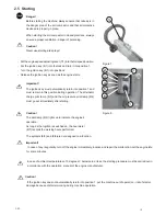
Page 15: ...evices are properly in place When starting the soil compactor in closed premises always ensure a proper ventilation danger of poisoning Caution Never use starting aid sprays Puttheenginespeedadjustinglever 7 1 intothefullspeedposition Put the ignition key 8 1 into the lock and turn it into position 1 Turn the ignition key 8 1 into position 2 Release the ignition key as soon as the engine starts Im...

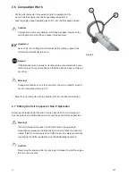
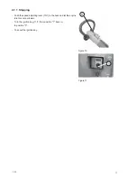
Page 16: ...t slip out of control Warning During work breaks even if they are short the soil compactor must be put out of operation refer to 2 7 Steer the soil compactor with the handle 9 2 into the desired direction 2 7 Putting the Soil Compactor Out of Operation Before work breaks and at the end of every day s shift the soil compactor must be parked on a stable base which should be as horizontal as possible...

Page 17: ...1 Stopping 1 1 Figure 10 Figure11 Push the speed adjusting lever 10 1 to the back and let the engine idle for some minutes Turn the ignition key 11 1 from position 1 back in to position 0 Take out the ignition key ...

Page 18: ...and disposed off according to the relevant environmental protection regulations Prior to any work on parts which are not protected the engine must be secured against unintentional starting After completion of service work all protective devices must be properly installed again Modifications and Retrofittings For safety reasons any modifications and retrofittings made on the soil compactor without ...

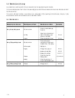
Page 19: ...Interval Maintenance Point Maintenance Work Remarks Every 8 operating hours Whole machine Check for visible damage leaks etc Air filter Clean the air filter element check it for damage and replace it if required 3 3 2 Engine Check the engine oil level 2 4 2 Every 150 operating hours Whole machine Check all screwed connections for tight seat retighten them if necessary All bare parts Slightly oil E...

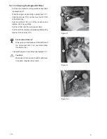
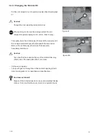
Page 20: ...ntally friendly manner Danger Danger of scalding because of hot oil Undo the screws 12 2 to remove the cover 12 1 Pull out the oil dipstick 13 1 Undo the protective cap 13 2 Screw the oil drain hose 14 1 onto the drain valve 14 2 and completely drain the engine oil Important Screwing the drain hose down opens the drain valve oil escapes Undo the oil drain hose 14 1 Put the protective cap 13 2 onto...

Page 21: ...filter 16 1 out of the crankcase and replace it by a new oil filter Put the oil filter into the crankcase 16a 1 Putthelid 15 2 ontothecrankcaseandfastenitby means of the screws 15 1 Environment Hazard Wipe up any oil and dispose of the oil filter and the oil soaked cloth in an environmentally friendly manner Topupwithengineoilaccordingtoparagraph3 3 1 Caution Make a short trial run and check for t...

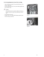
Page 22: ...er element 18 1 out of the air filter body 18 2 and blow or knock it clean Caution If this procedure does not provide a sufficient cleaning e g because of humid or oily dirt a new filter element must be used Insert the filter 18 1 again Put the cover 17 1 on the air filter body again and firmly close the body with the screw 17 2 Figure 17 Figure 18 1 2 1 2 ...

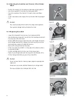
Page 23: ... and completely drain the tank Remove the clip 19 4 from the fuel filter 19 3 and replace the used filter by a new one Put the fuel lines 19 1 on the fuel filter and fasten them with the clips 19 2 Immediately wipe up any escaping fuel dispose of the fuel soaked cloth in an environmentally friendly manner Make sure that the clips are correctly fastened and check the system for tightness 2 1 2 3 4 ...

Page 24: ...lutch 22 2 and remove it from the clutch Screw a M20x100 hexagon head cap screw with through thread into the centrifugal clutch 22a 1 Remove the clutch from the cone of the driving engine by means of the M20x100 screw Remove the screw 22b 3 from the clutch At first mount the V belt 22b 1 on the pulley of the vibrator and then on the clutch 22b 2 Put the centrifugal clutch onto the cone of the driv...

Page 25: ... drain pan 23a 2 beneath the drain outlet Remove the oil drain plug 23a 3 from the base plate Completely drain the oil Caution Take care that the contact surfaces of the oil drain filler plug 23a 3 and of the base plate 23a 1 are clean Tilt the soil compactor Top up with gear oil through the oil filler oil drain opening 23a 3 refer to paragraph 3 4 for quantities and specifications Environment Haz...

Page 26: ...ceed as follows Remove the oil filler screw 25 2 of the switch head 25 1 Add hydraulic oil according to the specifications in paragraph 3 4 up to the middle of the sight glass 25 3 Handle in vertical position Fasten the oil filler screw 25 2 Bleed the hydraulic system by loosening the bleeding screw 26 2 at the reaction end housing 26 1 Firmly tighten the bleeding screw 26 2 again Check the oil le...

Page 27: ... 1 25 l SL 75 W 90 Hydraulic control Initial filling as required Fuchs TITAN ATF 3000 or equivalent Greasing points High pressure grease lithium saponified as required according to DIN 51825 KPF2 Battery as required Distilled water API GL 5 GL 4 Diesel Diesel according to DIN 51601 DK or BS2869 A1 A2 or STM D975 1D 2D Fully synthetic gear oil Fully synthetic gear oil DEXRON II D ATF 3 4 Consumable...

Page 28: ...ven in the column Remarks of the maintenance survey chart paragraph 3 and trouble shooting chart paragraph 4 2 allow a quick failure elimination on condition that the given order is precisely kept to when service work is carried out Any service work has to be made with appropriate tools and in accordance with the safety regulations set out in this operating and maintenance manual If a problem pers...

Page 29: ... as described 2 5 Lack of fuel Check the fuel level 2 4 1 Dirty fuel filter Replace the fuel filter 3 3 3 Dirty air filter Clean replace the air filter cartridge 3 3 2 No vibration no or insufficient forward travel Defective vibrator V belt Replace the vibrator V belt 3 3 5 Delayed control Air in the hydraulic control system Bleed the control system 3 3 7 ...

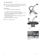
Page 30: ...erminals 28 1 At first disconnect the negative terminal Undo the screws 28 2 and take out the battery The installation is done in reverse order Figure 27 Figure 28 1 2 Figure 29 4 3 2Replacing the Fuse Put the soil compactor out of operation as described in paragraph 2 7 Remove the protective cap 29 1 of the fuse holder 29 2 Remove the fuse 30 1 from the fuse holder 30 2 Insert a new fuse 30 1 wit...

Page 31: ...n in accordance with your WEBER service 5 2 Removing Machine Preservatives Assembly Group Measure Remarks Whole soil compactor Thoroughly clean Check condition fastenings and tightness Have any failures ascertained repaired All bare parts Apply a slight film of grease or oil Fuel tank Add fuel up to the bottom edge of the filler neck 2 4 1 Engine Check the oil level if required add oil 2 4 2 In th...

Page 32: ...541839 info webermt nl in France WEBER Technologie SARL 26 rue d Arsonval 69680 Chassieu Telefon Telefax E Mail 33 0 472 791020 33 0 472 791021 france webermt com in Poland WEBER Maschinentechnik Sp zo o Ul Grodziska 7 05 830 Stara Wies Telefon Telefax E Mail 48 0 22 739 70 80 48 0 22 739 70 81 48 0 22 739 70 82 info webermt com pl in USA and Canada WEBER Machine USA Inc 40 Johnson Ave 112 Bangor ...

Page 33: ...ory Rollers Joint Cutters Internal Vibrators and Converters Vibrating Motors Stone Saws Rotary Trowels and many others Weber MASCHINENTECHNIK GmbH Im Boden D 57334 Bad Laasphe Rückershausen P O Box 2153 D 57329 Bad Laasphe Phone 27 54 398 0 Telefax 27 54 398 101 ...

Reviews: