background image

CR 9 CCD 2.0

Operation

Prior to starting work the owner of the compactor must be familiar with the work environment. The 

work environment includes obstacles in the work and traffic area, the bearing capacity of the ground, 

as well as the necessary safeguarding of the construction site in the area adjacent to public traffic; 

and it includes compliance with traffic regulations.

The soil compactor should only be operated when the protective fixtures are mounted. The protective 

fixtures must all be in functional condition.

At least once per shift the compactor must be checked for apparent defects. If there are apparent 

defects then operation of the compactor must be stopped immediately, and the responsible person 

must be informed. Prior to restarting, compactor malfunctions that have occurred must be corrected.

Always maintain adequate clearance to the edges of pits and embankments.

Do not drive at ninety degrees to slopes to prevent the compactor from tipping over.

After work has been concluded secure the compactor in accordance with statutory regulations, 

particularly in the area of public traffic surfaces.

Operation under difficult conditions

Never inhale the exhaust gas; it contains carbon monoxide, a colorless and odorless gas that 

is extremely hazardous, which, if inhaled even briefly, can cause unconsciousness and death. 

Therefore, never operate the engines in enclosed areas or in areas that are poorly ventilated 

(tunnels, caves, etc.). Exercise particular caution when operating the engine in the vicinity of 

people and livestock.

If lubricating oils and fuel come into contact with skin, they can cause skin cancer. Upon contact 

with the skin, clean affected skin with suitable cleaning agent without delay.

Maintenance and repair work

Only use 

original Weber spare parts

 to ensure reliable and safe operation for maintenance or repair 

work

.

Hydraulic hose lines must be checked at regular intervals in accordance with standard engineering 

practice, or they must be replaced at appropriate intervals, even if no signs of safety-relevant defects 

are present.

Adjusting tasks, service tasks, and inspection tasks must be executed on schedule in accordance 

with the service display in the COMPATROL display instrument or as specified in this operating and 

service manual. These activities should only be executed by instructed personnel.

For repair, service, or inspection work the engine of the compactor must be safeguarded against 

unintentional starting. 

All pressurized lines, particularly hydraulic lines and lines of the injection system of the drive motor 

must be depressurized before performing maintenance or repair tasks.

For maintenance and repair tasks the compactor must be parked on a level and stable substrate  

and must be secured from rolling off or tipping over.

Heavy components and assemblies must be secured to and lifted by hoisting machines that can  

bear their weight when they are replaced. Ensure that no hazard is caused by raising components  

or assemblies.

Do not position yourself or work under suspended loads.

Summary of Contents for CR 9 CCD 2.0

Page 1: ...and Maintenance Manual 0316 englisch bersetzung der Original Betriebsanleitung Weber Maschinentechnik GmbH Im Boden 5 8 10 D 57334 Bad Laasphe R ckershausen Germany Tel 49 0 27 54 398 0 Fax 49 0 27 54...

Page 2: ...2 CR 9 CCD 2 0...
Page 3: ...phic presentation 8 Device description 11 Technical data 12 Activities prior to starting work 14 Starting 16 Compacting 17 Shutting down 17 Maintenance overview 18 Maintenance work 19 Operating fluids...

Page 4: ...air and downtime costs and increase the reliability and service life of your compactor This operating and maintenance manual must always be available at the implementation site of the soil compactor I...

Page 5: ...is considered to be improper use for which the owner shall be exclusively responsible All liability is rejected if damage occurs due to non compliance with this provision This risk is borne solely by...

Page 6: ...ventilated tunnels caves etc Exercise particular caution when operating the engine in the vicinity of people and livestock If lubricating oils and fuel come into contact with skin they can cause skin...

Page 7: ...tches cable connections etc against water penetration by masking them off Cleaning tasks should only be executed in areas that are suitable and have been approved for this purpose oil separator amongs...

Page 8: ...MDM 1 Engine no image 9 Gas lever 2 Rocker switch 10 Attachment plates 3 Manual guidance rod 11 Fuse holders no image 4 Lifting ring 12 Hearing protection sticker 5 Handle 13 Maintenance cover 6 Base...

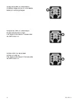
Page 9: ...mediately Error must be corrected prior to restart Graphic presentation MDM motor protection When the ignition is switched on the LED 1 will light up 10 hours prior to the next scheduled maintenance T...

Page 10: ...w or not available Battery is not being charged Temperature LED 1 is illuminated Engine temperature too high The engine is shut down 3 minutes after the LED comes on Air filter LED 1 is illuminated Ai...

Page 11: ...Use the gas lever to vary the engine speed between idle and full throttle Forward and reverse is variably controlled via the rocker switch attached to the manual guidance rod Function of the engine s...

Page 12: ...stroke diesel Operating speed 1 min 2900 Operating speed ground dependent in m min 28 Incline capacity ground dependent in 35 Vibration System Two wave vibrator Drive concept Mechanical Frequency in H...

Page 13: ...CR 9 CCD 2 0 13 2 1 3 4 5 6 1 Description 2 TYPE 3 Serial number 4 Year of construction 5 Mass 6 Rated power kW...

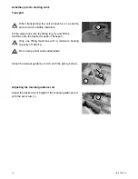
Page 14: ...sport Only use lifting machines with a minimum bearing capacity of 1000 kg When transporting the soil compactor on a vehicle secure it with suitable restraints Do not step under suspended loads Arrest...

Page 15: ...en the min and max marks min max Check the fuel level Open the cover 1 unscrew and remove the gas cap 2 check the fill level and if necessary top off with clean fuel to the lower edge of the filler ne...

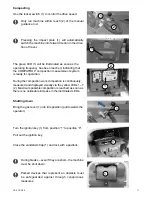
Page 16: ...ition is switched on the COMPATROL compaction system will perform a function test All LEDs 1 light up Insert the ignition key 1 and turn to position 1 10 hours prior to the next scheduled maintenance...

Page 17: ...ready for operation During the compaction work compaction is continuously measured and displayed visually via the yellow LEDs 1 7 2 Maximum possible compaction is reached as soon as there is no notic...

Page 18: ...egulations of the engine manufacturer must be complied with in addition to the above main tenance overview If lubricating oils and fuel come into contact with skin they can cause skin cancer Upon cont...

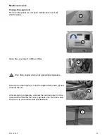
Page 19: ...e cover cap 1 of the oil filter Only drain engine oil when at operating temperature Screw the oil drain pipe 1 onto the engine drain valve 2 and drain off the oil After emptying completely unscrew the...

Page 20: ...ing agent without delay Clean change air filter cartridge Unscrew the air filter cover 1 Remove the air filter insert 1 from the air filter enclosure Clean air filter insert as specified by the engine...

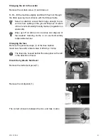
Page 21: ...oil in an environmentally friendly manner regulation on waste oils Wipe up off oil slick and oil residue and dispose of fuel soaked cleaning cloths in an environmentally responsible manner Changing th...

Page 22: ...22 CR 9 CCD 2 0 1 1 Checking the V belt Remove the V belt guard 1 Check the V belt 1 for cracks damaged flanks and wear If there is excessive wear replace the V belt as specified in the repair manual...

Page 23: ...or CCMC D4 D5 PD2 1 9 l Fuel tank Diesel Diesel in accordance with DIN 51601 DK or BS2869 A1 A2 or STM D975 1D 2D 10 0 l Exciter Fully synthetic transmission fluid API GL 5 GL 4 First filling Fuchs T...

Page 24: ...d fuse defective Execute start process as prescribed Check the fuel level Change the fuel filter See Hatz operating manual section 4 1 4 Clean change air filter cartridge Remove charge battery replace...

Page 25: ...level mark Check air filter clean replace if necessary Check fuel filter change if necessary All bare parts accelerator accelerator control cable fastening bolts Oil grease Starter battery if there is...

Page 26: ...socket Insert plug 1 into the charging socket Connect the battery charger to the mains Comply with the device manufacturer s operating manual for use of the battery charger The operating manual of th...

Page 27: ...e webermt com in Poland WEBER Maschinentechnik Sp zo o Ul Grodziska 7 05 830 Stara Wies Telephone Fax E mail 48 0 22 739 70 80 48 0 22 739 70 81 48 0 22 739 70 82 info webermt com pl in the Czech Repu...

Page 28: ...ion plates Vibrating tampers Vibration rollers Joint cutters Internal vibrators and converters Rollers Weber MASCHINENTECHNIK GmbH Im Boden 57334 Bad Laasphe R ckershausen Telephone 49 0 27 54 398 0 F...

Reviews:

Related manuals for CR 9 CCD 2.0