


13 -
User manual
The machine may only be operated by trained personnel who are familiar with the safety regulations.
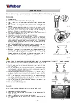
Disassembly
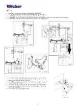
1. Deflate the tire.
2. Remove old balance weights from the rim (Fig. 20)
3. Insert the wheel into the bead breaker in such a way that it cannot damage
the rim.
4. Make sure there is no danger of crushing persons when operating the bead
breaker.
5. The tire must be pushed far enough into the rim cavity. Make sure that the
rim and rim flange are sufficiently treated with mounting paste (Fig. 21).
The sufficient use of mounting paste facilitates the disassembly and
assembly of tires and reduces the pressure on the machine.
6. Repeat the printing procedure on each side of the wheel several times until
the tire is completely loose on the rim.
7. Clamp the rim firmly with the claws on the clamping plate.
8. When the rim is placed on the clamping table, a clamping claw position
must be selected that does not cause damage to the rims. Mounting from
the outside or inside is possible (Fig. 22/23). Attention: Inner tension of light
metal rims is strongly discouraged; the manufacturer or his representatives
accept no liability for damage caused (e.g. to rim edges & inner rims) by
incorrect clamping choices.
9. Make sure the tensioned rims are tightened by all 4 clamping claws. This
ensures that the rim/wheel is centered on the mounting plate.
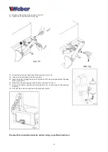
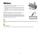
10. The complete mounting column can be tilted with the pedal to the working
position.
11. By means of a handle on the horizontal arm and by pressing down on the
mounting shaft, the mounting head must be brought into the working
position close to the rim (Fig. 24) and locked by pressing a button on the
handle. During the locking process, the mounting head moves back 1-2
mm so that the rim cannot be damaged if it is exactly positioned.
The position of the mounting head is set at the factory by default. For special rims >12 "and <18", it may be necessary
to mount the mounting head in a different position on the hexagonal shaft.
12. Pull the bead over the rim flange on the mounting head using the bead
lever ("tire iron").
13. Use the pedal to turn the mounting plate clockwise. The bead lever ("tire
iron") should be held briefly. Make sure that the rotation and lifting of the
tire does not cause a pinch hazard (Fig. 25).
14. Lift the tire completely and place the lower bead on the mounting head in
such a way that you can also remove it without using the bead levers ("tire
iron").
15. Operate the pneumatic control on the handle of the horizontal arm and
unlock the horizontal and vertical locking of the mounting head. The
mounting head is released by the spring tension.
16. Use the pedal to flip the column backwards, so that you can use tires and
rims without obstructing the
17. You can remove the clamping table.
Assembly
Before starting mounting, make sure that the tire and rim sizes match.
1. Clamp the rim to the clamping table.
2. Apply sufficient mounting paste to the inside of the rim as well as to the
upper rim flange.
3. Place the tire over the rim with the outer side facing up.
4. The heels should also be smeared with mounting paste (inside and
outside!).
Summary of Contents for 1228 Monster
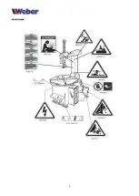
Page 4: ...4 Hazard signs...
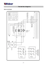
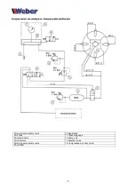
Page 15: ...15 Connection diagrams Electric circuit diagram...


