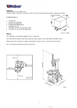
background image


8 - 

Structure 


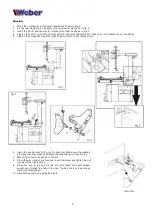
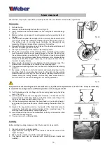
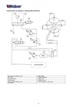
1.  Move the vertical arm to its desired position as shown in Fig. 5.  

2.  Fix the rear hinge pin (1), washers (2) and screw (4) as shown in Fig. 6. 

3.  Insert the pin (5) and the disc (6) into the tilt cylinder as shown in Fig. 7. 

4.  Tighten the nut (7) so that the cylinder and arm can work without friction. Take care not to tighten the nut too tightly.  

5.  Tighten the screw with a washer (8) as shown in Fig. 8 to secure the cover.  


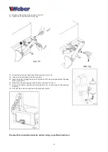
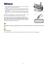
6.  Insert the pusher shovel (R) into the print arm. Make sure the washers 

are placed on both sides and tighten the self-locking nut (see Fig. 9). 

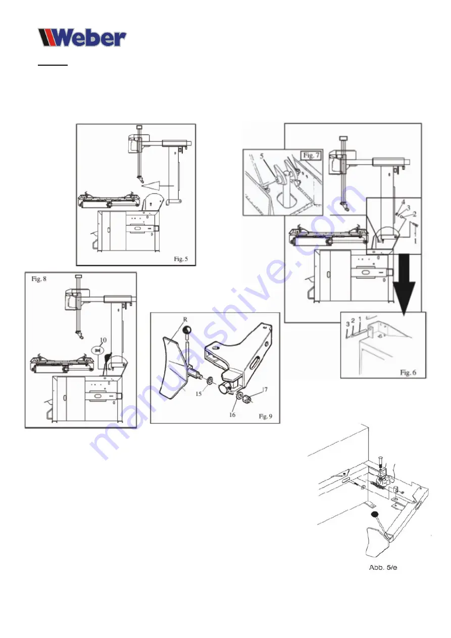
7.  Mount the print arm as shown in Fig. 5/e. 

8.  Place the arm in the correct position, insert the screw and tighten the nut 

loosely without tightening it. 

9.  Place the pen in the hole on the arm and insert the bead breaker 

suspension through the hole in the pen. Tighten the 2 screws loosely 

without tightening them.  

10.  Attach the spring to the indicated points. 


Summary of Contents for 1228 Monster

Page 1: ...ual Tire Changer Weber Expert Series 1228 Monster Weber 140203 Version 2 2 February 2018 www weber werke deWeber GmbH S lzbach 1 D 37293 Herleshausen Tel 49 0 5654 343 Fax 49 0 5654 794 info weber wer...

Page 2: ...l Specifications Page 12 Maintenance Page 12 User manual Page 13 Disassembly Page 13 Assembly Page 14 Connection diagrams Page 15 Diagram electric cabling Page 15 Pressure air supply schedule Page 16...

Page 3: ...ng to correct the interference All work on electrical connection and conversion may only be carried out by a qualified electrician in accordance with the regulations of the local professional associat...

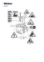
Page 4: ...4 Hazard signs...

Page 5: ...__________________________________ Expert name ____________________________________________ Address expert ____________________________________________ ____________________________________________ CAU...

Page 6: ...6 EC Declaration of Conformity Responsible technical file Herr Andr Popp S lzbach 1 D 37293 Herleshausen OT Nesselr den...

Page 7: ...ith pressure gauge Beadlight tire iron Plastic fasteners for tensioning claws 4 pcs Instructions for use on external packaging Drafting The 1228 Monster tire changer is designed for use in workshops T...

Page 8: ...e screw with a washer 8 as shown in Fig 8 to secure the cover 6 Insert the pusher shovel R into the print arm Make sure the washers are placed on both sides and tighten the self locking nut see Fig 9...

Page 9: ...hine 15 Insert the hose through the hole on the back of the machine and attach the hose to the connection 16 Attach the pressure gauge to the column as shown in Fig 6 17 Put the connection spiral hose...

Page 10: ...tion of rotation of the electric motor is not correct damage will occur within a few seconds for which the manufacturer supplier is not liable After complete assembly of the machine and checking the f...

Page 11: ...arts between the tensioning claws and the rim Never grip the moving clamping claws In order to avoid accidents while printing the belt the clamping claws should always be retracted to their closed pos...

Page 12: ...d acid free oil for compressed air tools Thorough cleaning of all moving parts of the mounting plate Fig 16 Light lubrication ensures proper functioning of the clamping jaws Check all screw and bolt c...

Page 13: ...ns of a handle on the horizontal arm and by pressing down on the mounting shaft the mounting head must be brought into the working position close to the rim Fig 24 and locked by pressing a button on t...

Page 14: ...m and tire sizes it is not necessary to change the adjustment of the mounting arm and head After the tire is mounted the tire can be inflated with the tire filler Fig 27 The air injection system can b...

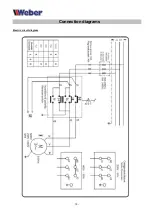
Page 15: ...15 Connection diagrams Electric circuit diagram...

Page 16: ...16 Compressed air circuit diagram...

Page 17: ...Clamping table and Booster 3 Overpressure safety valve 10 Separation 4 Air tank 11 Pressure gauge 5 Solenoid valve 12 Pump unit 6 Pedal valve 13 Breather valve 8 Overpressure safety valve 14 Compress...

Reviews:

Related manuals for 1228 Monster