9 -
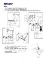
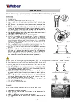
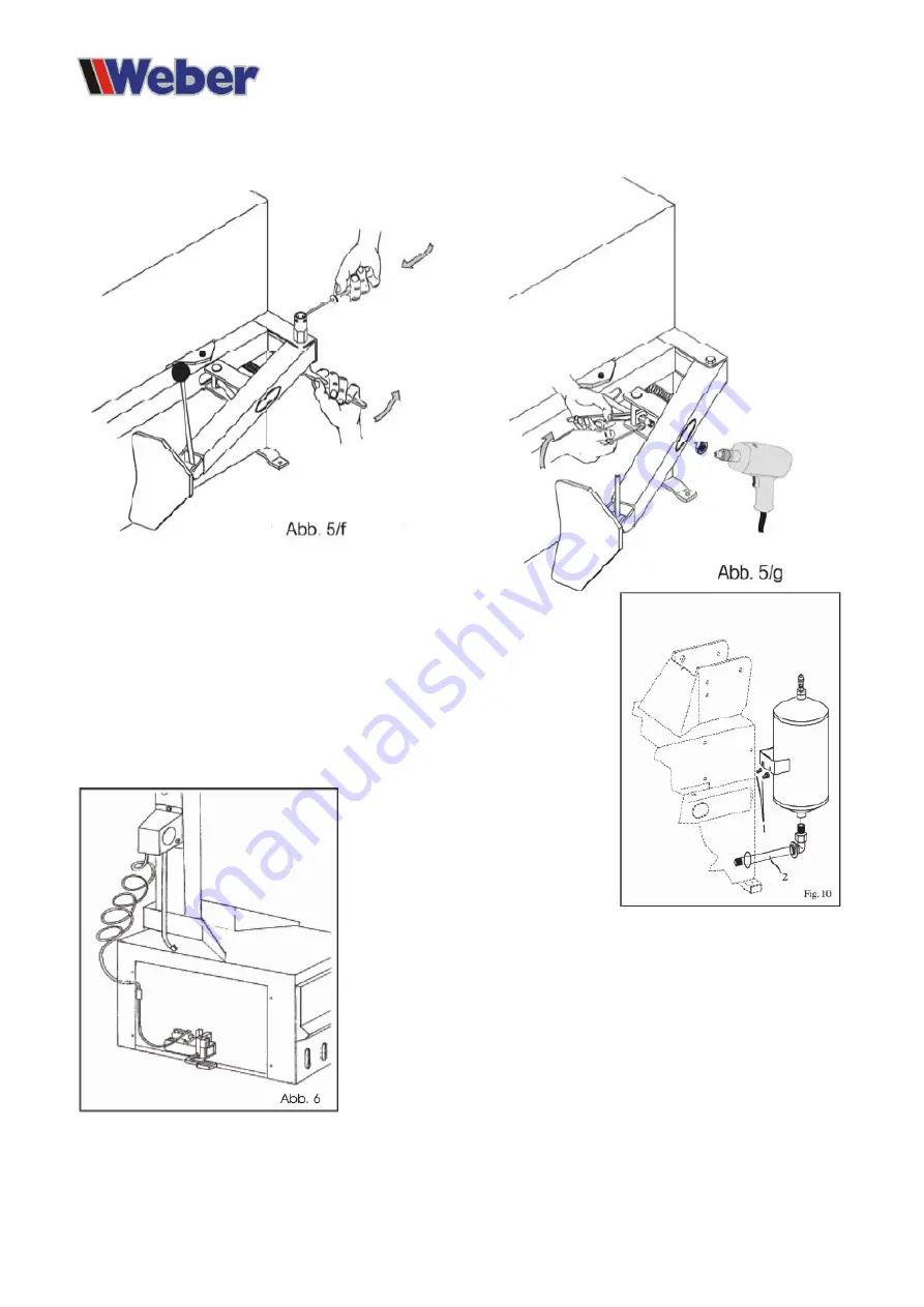
11. Screw on the print arm as shown in Fig. 5/f.
12. Tighten the nut as shown in Fig. 5/g.
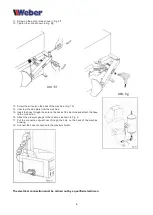
13. Screw the air tank on the back of the machine. (Fig. 10)
14. Unscrew the side plate from the machine.
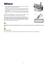
15. Insert the hose through the hole on the back of the machine and attach the hose
to the connection.
16. Attach the pressure gauge to the column as shown in Fig. 6.
17. Put the connection spiral hose through the hole on the back of the machine
housing.
18. Connect the hose connection to the pressure limiter.
The electrical connection must be carried out by a qualified electrician.
Summary of Contents for 1228 Monster
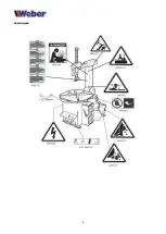
Page 4: ...4 Hazard signs...
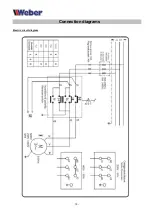
Page 15: ...15 Connection diagrams Electric circuit diagram...


