background image

Chapter 5 

Transport 


32708885 Geset 100


Version: 16.07.13


Page 28 of 77 

GB


5.  Transport 

Delivery 

The labeling station is normally delivered by a haulage contractor. Check the package for 
any  damage.  If  you  notice  anything  unusual,  notify  the  haulage  contractor  immediately 
and note it on the delivery slip. 


Scope of the delivery  

The elements of the system delivery depend on the selected options and the customer's 
specific  application.  When  the  system  is  delivered,  check  to  see  if  everything  is  there 
against the delivery slip. 


Transportation and unpacking    

Safety instructions 


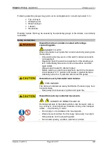
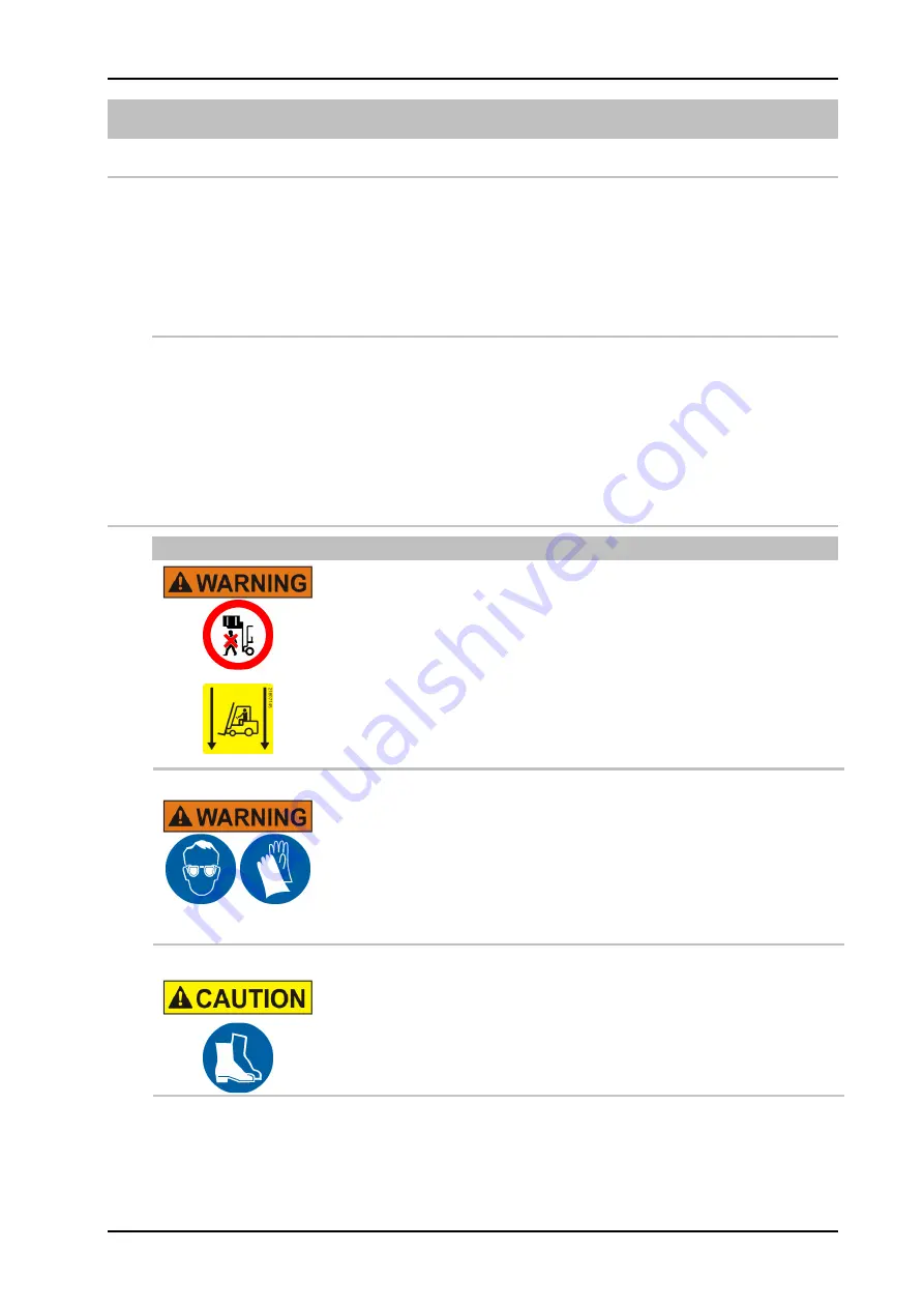
Hazard from lifted loads.


Falling loads can cause severe injury or death. 


-  Do not walk under a lifted load. The load may not be tilted. 
-  The location of the center of gravity must be taken into account 

when transporting the system. Loads with displaced center of 
gravity have special markings for the targeted placement of ma-
terial handling equipment. 


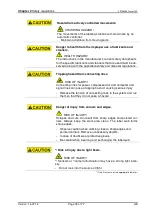
Hazard from tight straps.


The straps are secured tightly and can snap off if they are cut and 
cause severe injury. 


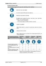
-  Wear protective glasses and gloves. 
-  Stand to the side outside of the hazard zone. 


Hazard from falling parts.


-  Wear protective footwear.  


The transport will be arranged by a Technician of the Bluhm Weber Group or by authori-
zed specialists. 
 

Summary of Contents for Geset 100

Page 1: ...on and Maintenance Geset 100 Article number of documentation 32708885 Copyright Weber Marking Systems GmbH Weber Marking Systems GmbH Maarweg 33 D 53619 Rheinbreitbach E Mail info webermarking de http www webermarking de Version 16 07 13 KRA 32708885 ...

Page 2: ...Blank page ...
Page 3: ... to the labeling system 16 Safety instructions 17 Remaining risks 19 Warnings on the labeling system 19 Obligations of the operator 20 Authorized persons 20 Personal protective gear 21 Protection Devices 22 Labeling station s cover 22 Main switch 22 Emergency Stop Push Button 22 Workplaces for the operating personnel 23 Waste disposal 23 3 Specifications 24 Information on operator elements 24 Nois...

Page 4: ...l adjustment 50 Adjust pusher roller brush and squeegee 52 8 Operation 55 Safety instructions 55 Turn on and off labeling machine 55 Control element Pushbutton box 56 Turn on labeling operation 56 Stop labeling operation 57 Putting the system out of service 57 Operation of labeler 58 9 Maintenance 59 Safety instructions 59 Daily servicing after appr 8 hours of operation 60 Weekly servicing after a...

Page 5: ...set 100 Version 16 07 13 Page 5 of 77 GB Safety instructions 72 Mechanical error 73 Correcting Adjustments based on labeler result 74 Correct labeling 74 Error at labeling 74 11 Index 76 12 EC Declaration of conformity 77 ...

Page 6: ...bility for damage arising from the following Nonobservance of operating instructions Improper use Use of untrained personnel Independent changes to the system The use of spare parts that have not been approved by the manufacturer The following apply The obligations agreed in the supply contract general terms and conditions the manufacturer s delivery conditions as well as the statutory regulations...

Page 7: ...of the conventions for the text and illustrations which are used in this manual Buttons switches and pushbuttons that need to be pressed are placed in brackets Ex Press the Start button to accept the changes Menu points and links to chapters and keywords are places in Ex The pushbutton Turning plate infeed outfeed passage Procedures that need to be performed in a fixed sequence have to be num bere...

Page 8: ... of the problem All the information from the labeling system rating plate Did the problem arise for the first time after the following After inserting a new role of labels or ribbon After changing the system configuration If the malfunction arose in the print apply cycle all of the information about the PLC signal status Before contacting our hotline check if the operating instructions chapter tit...

Page 9: ...ed See explanations Tamp on tamp blow blow on and wipe on Automatic mode See labeling operation Base conveyor See also conveying system The base conveyor trans ports the products that should be labeled Blow on Contact less application mode in which the tamp receives the printed label by a vacuum and blows it onto the product without the tamp moving Conveying system The unit consisting of the conve...

Page 10: ...m Labeling system Dispensing system for automatically applying labels Labeling operation This is the same as automatic mode The labeling system is ready to print and dispense labels Labeling system The labeling system is used to label products automatically and consists of several components assembly groups e g conveyor belt labeling system LED Light emitting diode Low label prewarning Low Label w...

Page 11: ...ts to the customer s con veying system Here the products are removed Service unit FR group This unit consists of A gauge for displaying the compression of the compressed air in bar Quick action stop valve Water trap for manually draining any con densate Start sensor See also Product sensor The start sensor scans the lead ing edge of the product As soon as a product is detected the labeling procedu...

Page 12: ...Chapter 1 General information 32708885 Geset 100 Version 16 07 13 Page 12 of 77 GB Term Explanation VDC Direct current voltage Water trap See service unit ...

Page 13: ...rm of text and symbols to warn of hazards and provide instruction for preventing any personal injury and property damage Safety instructions are introduced by keywords that express the extent of the danger Safety instructions can be affixed directly on the labeling system or in documents pertain ing to the labeling system Meaning of the hazard levels The symbol indicates a hazardous situation that...

Page 14: ...m is used with an additional pneumatic shutter at the aperture for the tamp when operating in a wet environment the labeling system has additional air conditioning features in the stainless steel cabinet for use in an aggressive air environment e g salted air the labeling system has additional air conditioning features in the stainless steel cabinet for use in a dusty environment with unadjusted p...

Page 15: ...explosive atmosphere When the labeling system comes into contact with food Modifications and alterations to the labeling station If the machine is independently modified and altered all of the manufacturer s liability and warranties will expire This also holds true for modifications and changes to the programs of the programmable control system as well as changes to the parameters to control de vi...

Page 16: ...regulations 32708885 Geset 100 Version 16 07 13 Page 16 of 77 GB Hazards to the labeling system Fig 2 1 Example for hazards to the labeling station Geset 114 Fig 2 2 Example for hazards to the labeling station Geset 121 ...

Page 17: ...e care of loose connections and dam aged cables Always keep the switch cabinet locked Before working on electrical equipment switch the miniature circuit breaker to 0 position and secure it against being ac cidentally turned on If possible disconnect the power Hazard from easily flammable label material FIRE HAZARD The ribbon and labels are easily flammable Potential injury from fire and smoke Kee...

Page 18: ...onnecting lines for power compressed air and computer and signal lines can pose a tripping hazard causing serious injury Release the tension of connecting lines to the system and run them so that they do not pose a hazard Danger of injury from corners and edges RISK OF INJURY Scrapes and cuts can result from sharp edges and pointed cor ners Always keep the work area clean The label web forms sharp...

Page 19: ...our safety aware ness and avoid accidents To prevent hazards observe the special safety instructions and each chapter When connecting the labeler to the customer s conveying system there may arise hazard areas at the transitions Suitable protection measures have to be ar ranged in this case Warnings on the labeling system Special hazards arising from the labeling system are identified with yellow ...

Page 20: ...abeling station are repaired by trained personel or by Techni cians of the Bluhm Weber Group The qualified personel is trained in handling the integrated controller before pa rameterizations may be arranged If you do not understand parts of this manual we kindly ask you to contact imme diately your contact person at Bluhm Weber Authorized persons Authorized persons according to this manual are fol...

Page 21: ...ts watches or similar SAFETY GLASSES Wear safety glasses to protect from splashing cleanser and flying parts PROTECTIVE GLOVES Wear protective gloves to protect from sharp edged objects and irritating detergents Wear personal protective gear for the following activi ties Protective work clothes Protective footwear Protective gloves Safety gog gles Transport labeling station X X X Put up labeling s...

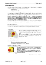
Page 22: ...the customer s conveying system may evoke dangerous areas at the transi tions Suitable safety measures have to be taken in this case Labeling station s cover The fixed and screwed system covers protect the user against mechanical hazards Main switch Fig 2 3 Main switch with lock The main switch serves for switching the system on and off In position 0 it interrupts the power supply to the system bu...

Page 23: ...and troubleshooting remove the label from the applicator etc the labeling system can be operated from all sides Only one person is permitted to replace the consumable material All interventions are only permitted when the labeling system has stopped operation After troubleshooting and or restarting the labeling station the operator must im mediately leave the hazardous area and has to stay in the ...

Page 24: ... roll Power connection 115 230 V 50 Hz Power consumption depending on version 1 5 kW Protection class IP 40 Ambient temperature 10 38 C Surrounding conditions 20 90 relative humidity non condensing Information on operator elements Pushbutton unit Geset 100 1 illuminated pushbutton and 1 button and 1 Emergency Stop Pushbutton HMI Labeler Operator panel or display s Alpha s manual Noise level The A ...

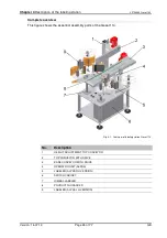
Page 25: ... application one or both outsides receive one label in so called Wipe On procedure when the product passes by When the label is applied the labels are often pushed on by a pusher pusher brush squeegee or rolls The conveyor belt moves the completely labeled products to the outfeed area Here the products are removed manually or be the customer specific conveying system Wrap around labeling Geset 121...

Page 26: ... shows the essential assembly parts of the Geset 114 Fig 4 1 Overview of labeling station Geset 114 No Description 1 HEIGHT ADJUSTMENT TOP CONVEYOR 2 TOP CONVEYOR WITH DRIVE 3 BASE CONVEYOR WITH DRIVE 4 OPERATOR UNIT ALPHA 5 LABELER ALPHA RH VERSION 6 SWITCH CABINET 7 GIMBAL LABELER 8 PRODUCT GUIDANCES 9 LABELER ALPHA LH VERSION ...

Page 27: ...is figure shows the essential assembly parts of the Geset 121 Fig 4 2 Overview of labeling station Geset 121 No Description 1 PUSHER PLATE SPONGE RUBBER 2 WRAPPING UNIT WITH DRIVE 3 SWITCH CABINET 4 LABELER LH VERSION 5 GIMBAL LABELER 6 OPERATOR UNIT ALPHA 7 BASE CONVEYOR WITH DRIVE 8 PRODUCT GUIDANCES ...

Page 28: ...ation and unpacking Safety instructions Hazard from lifted loads Falling loads can cause severe injury or death Do not walk under a lifted load The load may not be tilted The location of the center of gravity must be taken into account when transporting the system Loads with displaced center of gravity have special markings for the targeted placement of ma terial handling equipment Hazard from tig...

Page 29: ... is It is standing on a pallet It may be wrapped with stretch film or in a transport box It may be secured with additional straps and the plate feet may be screwed to the pallet Access ways to the machine are sufficiently dimensioned and not blocked Required equipment Suitable means transport double pallet trucks or forklifts with a minimum capaci ty of 1000 kg When using a forklift drive slowly U...

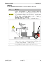
Page 30: ...m Weber Group The straps are secured tightly and can fly back when they are cut and cause injury 2 Open if available the transport box applied notes have to be observed Remove any film and straps if available 3 Remove if available all transport securing devices from the rubber feet Fig 5 2 Lift labeling system from pallet 4 Lift the labeling system with a suitable material handling equipment in sh...

Page 31: ...cedure 1 Remove the label material from the system 2 Transport the system to its storage location For securing and transporting the labeling system follow the safety instructions in the above section Transportation and unpacking 3 To protect from dust cover the labeling system with a cotton or paper cloth To prevent the formation of condensate do not use film 4 Climatize the storage location like ...

Page 32: ...s are adapted to the surrounding conditions To make these fine adjustments detailed professional knowledge is necessary that arises from experience with labeling systems This required professional knowledge cannot be completely communicated by the operat ing instructions therefore a Technician from the Bluhm Weber Group needs to perform the installation or accept the labeling system in a final ins...

Page 33: ...Transport on page 28 near the labeling site in the area of the installation site The base is solid level and flat The labeling system and if applicable the turning plate must be completely in stalled The connections for the compressed air and electricity are close to the labeling site maximum distance of 1 5 m as specified in the chapter Specifications on page 24 Required equipment Flat wrench Spi...

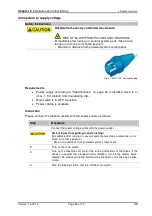
Page 34: ...ling site Main switch is in OFF 0 position Power cabling is available Instruction Please connect the labeling system with the power supply as follows Step Procedure 1 Connect the power voltage cable with the power socket Risk of injury from pulling in and crushing Immediately after turning on several system parts make a reference run or move to its home position Maintain a distance from powered sy...

Page 35: ...y an automatic controller in automatic operation Maintain a distance from moving parts Danger of being pulled in by rotating elements DANGER OF BEING PULLED IN Rotating elements at the labeling system like transport side or top conveyor chain alignment unwinder drive rollers or feed rollers are powered by a motor Do not grip in at or between the moving parts Wear only tight clothes with low tensil...

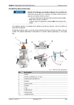
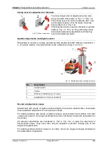
Page 36: ...f position Tighten again the respective interlock after the change of po sition The labeling station is provided with different positioning devices and its handling is described in advance Screwings without grip or similar are mountings that may normally not have to be ad justed The gimbal adjustment is described in a section below separately s from page 50 Fig 7 1 Examples for positioning device ...

Page 37: ... e at a crank rotation the spindle slide covers a distance of resp 2 or 4 mm Fig 7 3 Spindle adjustment with digital counter No Description 1 CLAMP LEVER 2 CRANK 3 DIGITAL COUNTER mm 1 10 mm 4 NUMBERING OF THE ADJUSTMENT Record of adjustment values Adjustments with scales or digital counters simplify the position determination and enable thus repeatable adjustment for each product charge For label...

Page 38: ... products Labeling system is connected to power Triggering of the labeling system is pos sible by product sensor or I O interface Instruction Please put the labeling system Geset 114 into operation as follows Step Procedure 1 If there are already exist notes of the adjustment values ref page 37 for the product to be labeled the values should be available 2 Adjust base conveyor s from page 40 3 Adj...

Page 39: ...f page 37 for the product to be labeled the values should be available 2 Adjust base conveyor s from page 40 3 Adjust side guidance s from page 41 4 Adjust wrapping unit s from page 44 5 Insert label roll in labeler s from page 46 6 Adjust product light barrier s from page 46 7 Change peeler plateChange peeler plate s from page 47 8 Positioning of peeler plate to product s from page 48 9 Pitch pee...

Page 40: ...base conveyor Fig 7 4 Pos 1 is installed fix The height of the base conveyor can be adjusted by the threads at the rubber feet Fig 7 4 Pos 4 of the switch cabinet Fig 7 4 Base conveyor and switch cabinet No Description 1 BASE CONVEYOR 2 DRIVE MOTOR 3 SWITCH CABINET 4 RUBBER FEET Requirements Power supply is turned off No transportation of products Required equipment Screw wrench for rubber feet ad...

Page 41: ...usted that between product and side guiding is a crack of appr 1 1 5 mm per side Fig 7 5 Examples of side guidances No Description 1 STAR GRIP SIDE GUIDANCE OPERATOR S SIDE 2 SIDE GUIDANCE WITH WEAR STRIP 3 DISTANCE PRODUCT 2 3 mm 4 STAR GRIP SIDE GUIDANCE DRIVE SIDE 5 SIDE GUIDANCE WITH RODS Requirements Labeling system is turned off 2 sample products No transportation of products Please adjust t...

Page 42: ... which the top conveyor is adjusted to the different product heights The top conveyor is used only for side labeling and has to be put up when not used so that products can pass without any contact Fig 7 6 Adjust top conveyor No Description 1 CRANK FOR HEIGHT ADJUSTMENT OPTIONAL 2 DIGITAL DISPLAY OPTIONAL 3 CLAMPING TO HEIGHT ADJUSTMENT INTERLOCK 4 TOP CONVEYOR 5 ALIGNMENT POINT FOR PRODUCT HEIGHT...

Page 43: ...inning and end a diagonal infeed or outfeed In order to adjust the top conveyor height to the product please position the product in the center ar ea of the slopes Fig 7 6 Pos 5 The right top conveyor height is achieved if the product is positioned tightly between both conveyor belts Fig 7 6 Pos 6 and it does not deform in doing so Requirements Power supply is turned off One or more sample product...

Page 44: ...y means of the rotati on and the counter pressure of the pusher plate pushed onto the product The counter pressure of the pusher plate and the wrapping unit the speed of the wrapping unit is twice as fast as the speed of the base conveyor put the product to rotation Fig 7 7 Wrapping unit No Description 1 BRACKET AND POSITIONING DEVICE OF FOAM RUBBER PLATE 2 PUSHER PLATE SPONGE RUBBER 3 WRAPPING UN...

Page 45: ...that the label is safely pushed onto the prduct 3 Check and correct this adjustment if necessary Information on adjustment of wrapping unit Depending on product and label the wrapping unit has to be adjusted in height Requirements Power supply is turned off One or more sample products No transportation of products Instruction Please adjust the wrapping unit as follows Step Procedure Crushing hazar...

Page 46: ...labeler to start the la beling process The point of time of the product detection is significant for the positioning of the label onto the product A delay value in the controller enables to change the label position exactly per each millimeter s Alpha manual The light barriers are installed at a fix position ex factory A position change is not requi red It is even undesired as it may impact the ap...

Page 47: ...ng the peeler plate The peeler plate Fig 7 9 Pos 1 is screwed with the bracket Fig 7 9 Pos 2 The complete peeler plate is fixed at the labeler s bracket Fig 7 9 Pos 4 After each chan ge an adaption of the peeler plate s position is necessary Fig 7 9 Change peeler plate No Description 1 PEELER PLATE 2 PEELER PLATE S BRACKET 3 MOUNTING SCREWS 4 LABELER S BRACKET 5 MOUNTING SCREWS PEELER PLATE Requir...

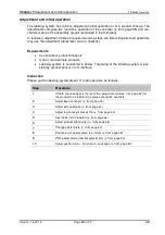
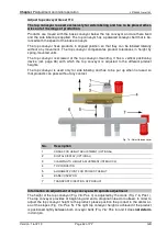
Page 48: ...nto the bracket Fig 7 9 Pos 4 and fix it with the screws Fig 7 9 Pos 5 5 Position the peeler plate to the product s next section Positioning of peeler plate to product After a product change the position of the peeler plate to the product may be adapted Use for adjustment of the peeler bar the positioning device of the labeler s page 36 Ad just thus the height distance and angle from peeler bar to...

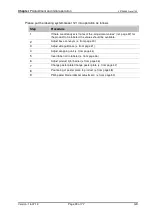
Page 49: ... 4 LABEL Requirements Side guidances s page 41 and chain alignment page 44 are correctly adjust ed Labeling system is turned on and ready for operation One or more sample products No transportation of products Please adjust the peeler plate to the product as follows Step Procedure 1 Place one product at the infeed passage of the system Hazards from actively controlled movements Maintain a distance...

Page 50: ...gimbal adjustment is available and an adaption is necessary please follow the description Gimbal adjustment pitch peeler blade from page 50 6 Let further products run in singly in the label system to check your adjust ment Pitch peeler blade Gimbal adjustment If it is necessary to adjust the pitch or to enable a tipping of the labeler resp The peeler bar labelers provide an additional so called gi...

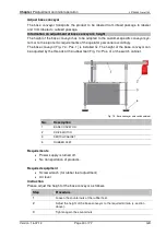
Page 51: ...ined personnel After adaption of the inclination an increase of the feed speed of the labeler may be necessary The figure on the righthand side shows the adjustment of the tamp pad for conical pro ducts The tamp pad has to be adjusted parallel to the product shape Fig 7 13 Inclination angle of peeler plate with gimbal Requirements All points of Change peeler plate from page 47 until step 5 are ful...

Page 52: ...t by the pushing of the squeegee Label and pro duct stick in the contact area of the squeegee at a flat surface This advantage has a par ticulary impact at products in Nolabel look and avoids viewable air entrapments A disa dvantage of the squeegee is the mechanical wear of label and product Fig 7 14 Example round bodied canister No Description 1 SQUEEGEE 2 PRODUCT CANISTER 3 CONVEXITY OF THE PROD...

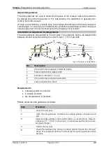
Page 53: ...d pusher have an identical width Only if pusher roller or brush do not lead to desired result the squeegee should be used Assumed there are no damages to be expected that are caused by mechanical wear Fig 7 15 Adjust pushers No Description 1 BASE CONVEYOR 2 PEELER PLATE 3 SQUEEGEE 4 PRODUCT 5 PUSHER BRUSH 6 PUSHER ROLLER 7 PUSHER FOAM ROLLER ...

Page 54: ...always to be symmetrical for a constant force distribution Observe when using squeegees that only the side with the rounded edges shows in direc tion to the product Pushers are powered by pushers that are often started by a pneumatic cylinder Pushers have to be extended completely for adjustment Therefore they may be pulled out manual ly if they are without compressed air Requirements The Position...

Page 55: ...arts Danger of being pulled in by rotating elements DANGER OF BEING PULLED IN Rotating elements at the labeling station like label liner rewinder label feed at labeler base conveyor and 2 top conveyor are driven by a motor Do not grip in at or between the moving parts Turn on and off labeling machine Fig 8 1 Main switch on The main switch of the machine is located at the switch cab inet s front To...

Page 56: ...ned off Material rolls at labeling system loaded and threaded Labeling system is connected to power and compressed air System was put into operation see chapter Installation and initial startup on page 38 Instruction Please turn on the labeling system for operation as follows Step Procedure 1 Turn on the main switch RISK OF INJURY FROM CRUSHING Maintain a distance from moving parts 2 Push the STAR...

Page 57: ...lers is curved which can cause prob lems with the operation mode This characteristic of the labels as well as the retained cur vature depend on the material which can vary significantly between the different print me dia The ambient conditions such as high temperatures and humidity enhance this effect Remove critical label material before long breaks and after end of work from labe ler Instruction...

Page 58: ...tion 32708885 Geset 100 Version 16 07 13 Page 58 of 77 GB Operation of labeler Information on operation of the labeler can be found in the manual of the labeler in the documentation referring to this labeling station ...

Page 59: ...s for the specific lubricants and cleaners that are used must be ob served along with the applicable safety and disposal regulations Repairs and servicing may only be performed by electrician when the device is turned off voltage free according to UVV 7 0 2 Para 3 Jobs that must be performed when the electri cal power and compressed air are still on may only be done by trained ex perts who are awa...

Page 60: ...he daily maintenance as follows Step Procedure 1 Arrange the required maintenance work at the labelers Description s cor respondent chapter in provided manual of Alpha 2 Check Base conveyor Top conveyor Pusher brushs squeegee or rolls Conveyor belts Product guidings and deflection rollers for label and adhesive residues Remove residues with label remover or alcohol Instruction s page 66 3 Examine ...

Page 61: ...follows Step Procedure 1 Clean all sensors product low label label gap sensor carefully with a soft brush and compressed air spray Instruction s page 63 2 Examine lines tubes screw connections valves cylinders and motors for leak tightness and or fixed seat Possible repairs have to be arranged immediately and professionally 3 Check Base conveyor Top conveyor Pusher brushs squeegee or rolls Conveyo...

Page 62: ...t may lead to damages 3 Check moving or rotating machine parts for bearing play Possible repairs have to be arranged professionally Annual servicing after appr 2000 hours of operation Requirements Labeler is without electrical power No transportation of products Required equipment Bearing grease Proline Pro 672U 92100772 food compliant Product recommendation Can be obtained from the Bluhm Weber Gr...

Page 63: ... SOLVENT FLUSENFREIES TUCH LINT FREE CLOTH REINIGUNGSFOLIE LAP SHEET BESTELLANNAHME ORDER PROCESSING TISCHDRUCKER DESKTOP PRINTER ETIKETTIERER LABELER DRUCKMODULE PRINT MODULES ETIKETTIERER LABELER DRUCKKOPF PRINTHEAD GUMMIWALZEN PLATEN ROLLERS SPENDEKANTEN PEELER BARS ANTRIEBSWALZE DRIVER ROLLER AUF ABSPULERACHSEN UN REWIND MANDRELS STÜTZLUFT EINHEIT AIR ASSIST ASSEMBLY FÜHRUNGSROLLEN GUIDE ROLLE...

Page 64: ...light sensors and barriers may be damaged when cleaning with compressed air steam cleaner aggressive dissolvers or scrubbing agents Do not use any liquids that may cause short circuits Do not use aggressive dissolvers or scrubbing agents Do not use hard or sharp edged parts for cleaning Maintain the optics of the light sensors and light barriers free of dust and grease Use for cleaning a smooth li...

Page 65: ...ed to belt s axis if possible The correction of the belt run is arranged by adjustment of the drive and deflection rollers The rolls on which the base conveyor runs have to be adjusted Requirements Labeler is without electrical power No transportation of products Instruction Please check the drive belts and conveyor belts as follows Step Procedure 1 Remove foreign objects and much dirt particularl...

Page 66: ...ll parts may get onto the rollers and tip The base conveyor and adjacent assembly parts have to be cleaned regularly and careful ly Requirements Labeler is without electrical power No transportation of products Required equipment Alcohol 21800915 and or roller solvent 21800977 Lint free cloth 21800978 Label remover 21800771 Product recommendation Can be obtained from the Bluhm Weber Group with the...

Page 67: ...transportation of products Instruction Please adjust the belt tension as follows Step Procedure 1 Apply two markings with a highest possible distance e g 500 mm at the upside of the base conveyor 2 Calculate the required lengthening of the base conveyor e g lengthening 500 mm 0 5 2 5 mm 3 Tense the base conveyor with both clamping nuts until the distance between the markings has increased by the c...

Page 68: ... distance that is not influenced by any deflection Requirements No transportation of products Emergency stop pushbutton is unlocked Labeling station is connected to power Labeling station was put into operation see chapter Installation and initial startup Instruction Please adjust the belt running direction as follows Step Procedure Risk of injury The examination of the belt running has to be arra...

Page 69: ...ed when a skipping of the timing belt at the pulley is not possbile anymore A belt tension that is too high can result in damages of the deflections bearings and timing belts At optimum belt tension the belt should be adjusted in center by 90 Requirements No transportation of products Labeling station is turned off Labeling station was put into operation see chapter Installation and initial startu...

Page 70: ...xchange the base conveyor as follows Step Procedure 1 Dismantle all assembly parts side guidings hopper aso that may impact the belt change 2 Dismantle the deflection plate with deflection roller that is located opposite to the roll of the drive timing belt 3 Put out the timing belt laterally Put in a new timing belt in revised order 4 Mount deflection plate with deflection roller 5 Reinstall if a...

Page 71: ...nstructions Hazard from incorrect spare parts Incorrect or faulty spare parts can impair safety and cause injury or damage to the machine Only use original spare parts or parts that are specifically ap proved by the Bluhm Weber Group Wiring diagram The wiring diagram is included in switch cabinet ...

Page 72: ...age conducting parts DANGER TO LIFE Before performing any work at the labeling station disconnect it from electrical power Hazards from actively controlled movements RISK OF INJURY FROM CRUSHING The movements of the labeling system are motor driven by an automatic controller in automatic operation Maintain a distance from moving parts Danger of being pulled in by rotating elements DANGER OF BEING ...

Page 73: ...ameters blow extension The desired rate of application can not be reached with the labe ler The required rate of application from the conveyor exceeds the specifications Check conveyor speed and the product gap Reduce conveyor speed if possible Incorrect configuration parameter values of the labeler Excessive cycle processing time Check the delay times Inquire Service Technician at the Hot line s ...

Page 74: ...g If the labeling is performed correctly the label is free from creases straight always at the same position on the product No correction is necessary Fig 10 1 Product with correct labeling result Error at labeling The label has creases Fig 10 2 Product with creases in the label Correct the labeling result as follows Step Procedure 1 The application speed of the label may be too fast Examine and c...

Page 75: ...osition changes from product to product Fig 10 4 Product with position displacement of the label Correct the labeling result as follows Step Procedure 1 The application speed of the label may be too high or too low Correct the application speed of the label 2 Examine and correct the sensor for product detection 3 Examine and correct the distance from peeler bar to product 4 Examine and correct the...

Page 76: ...32 Explosion Risk Area 14 Fine adjustments 32 Gimbal adjustment 52 Height and side adjustment of labeler 38 39 50 Hotline 8 Insert label roll in labeler 47 Inspection and maintenance list62 63 64 Installation 32 Label Out 10 Low Label 10 Maintenance instruction conveying systems 67 Operating personnel 23 Operation Outdoors 14 Overview 26 Pitch peeler blade 52 Program changes 15 Protection Device 2...

Page 77: ...otre responsabilité exclusive que la machine Geset 100 DE Seriennummern GB Serial number FR Numéros de série DE auf das sich diese Erklärung bezieht folgenden Bestimmungen und Richtlinien entspricht GB to which this declaration relates corresponds to the regulations and directives FR que concerne cette déclaration est conforme aux directives et réglementations suivantes 2006 42 EG 2004 108 EG 2006...

Reviews: