background image

3

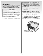
TYPICAL BULK PROPANE
GAS SUPPLY
INSTALLATION

Gas line piping

Refer to the piping chart at the bottom of the page.

The corrugated gas line from the manifold is 
48 inches long. Do not extend the gas line.

We have provided the means to make an SAE 45°
flare connection. Do not use pipe sealant on 
this connection.

If the length of line required does not exceed 50 feet,
use a 5/8" O.D. tube. One size larger should be used
for lengths greater than 50 feet.
Refer to piping chart below.

Gas piping may be copper tubing, type K or L;
polyethylene plastic tube, with a minimum wall
thickness of .062 inch; or standard weight (schedule
40) steel or wrought iron pipe.

Check you local building codes.

WE RECOMMEND THAT THIS INSTALLATION BE
DONE BY A LICENSED PROFESSIONAL.

General Specifications for Piping

Note - Contact your local municipality for building
codes regulating outdoor gas grill installations. In
absence of Local Codes, you must conform to the
latest edition of ANSI Z223.1/NFPA 54.

This grill is designed to operate at 10.5 inches of
water column pressure. A LP in line regulator may be
necessary to acheive this pressure.

CAUTION: If young children are in the area, a 

locking valve should be considered.

Pipe compound should be used which is resistant to the
action of liquid propane gas when gas connections 
are made.

The gas connections must be firmly attached to rigid,
permanent construction.

Note: The information provided in this manual is
general for typical installations. We cannot cover all
possible installation ideas. We recommend, prior to
installation, that you contact your municipality for
local building codes and your local fire department
for installation requirements.

If you have any questions, contact the Vieluxe

®

Customer Service Center at 1-866-VIELUXE.


(inches) 

(inches)  10 20 30 40 50 60 70 80 90 100 

125 

150  175 

200

  1/4 

.364 

32 22 18 15 14 12 11 11 10  9  8  8  7  6

  3/8 

.493 

72 49 40 34 30 27 25 23 22 21 18 17  15 14

  1/2 

.622  132 92 73 63 56 50 46 43 40 38 34 31  28 26

  3/4 

.824  278 

190 

152 

130 

115 

105 96 90 84 79 72 64  59 55


1.049 

520 350 285 245 215 195 180 170 160 150 130 120  110 100

  1 

1/4  1.380  1050 730 590 500 440 400 370 350 320 305 275 250  225 210

  1 

1/2  1.160  1600 

1100 890 760 670 610 560 530 490 460 410 380  350 320


2.067  3050 

2100 

1650 

1450 

1270 

1150 

1050 990 930 870 780 710  650 610


1/2 

2.469 

4800 3300 2700 2300 2000 1850 1700 1600 1500 1400 1250 1130 

1050 980


3.068 

8500 5900 4700 4100 3600 3250 3000 2800 2600 2500 2200 2000 

1850 1700


4.026 

17500 

12000 9700 8300 7400 6800 6200 5800 5400 5100 4500 4100 

3800 3500


Nominal

 Iron 

Pipe Interal

 Size 

Diameter

 Length of Pipe (Feet)

  Table 10-1 

Maximum Capacity of Pipe in Cubic Feet of Gas per Hour for Gas Pressures of 0.5 psi or Less and


a Pressure Drop of 0.3 Inch Water Column.


(Based on a 0.60 Specific Gravity Gas)

©1997 National Fire Protection Association, Inc., and International Approval Services - U.S., Inc.  All Rights Reserved.

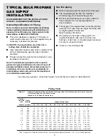
Piping Chart

Summary of Contents for Vieluxe 27 Built-In Grill

Page 1: ...ble location for your Vieluxe gas grill installation give attention to concerns such as exposure to wind proximity to traffic paths and keeping any gas supply lines as short as possible Never locate the Vieluxe gas grill in a garage breezeway shed under an unprotected overhang or other enclosed area Locate the grill and structure so there is enough room to safely evacuate the area in case of a fir...

Page 2: ...t for a rotisserie it should be on the left side of the structure Figure 3 All dimensions are to finished surfaces BUILT IN GAS LINE LOCATIONS A C B Front View Front of Grill Structure Plan View 27 grill 39 grill Tolerances A 4 4 B 7 7 C 2 5 2 5 DIMENSIONS 1 8 1 8 1 8 1 8 1 8 1 8 VIELUXE BUILT IN GAS LINE LOCATIONS Area should be kept clear of sharp jagged or extremely abrasive surfaces to avoid p...

Page 3: ... rigid permanent construction Note The information provided in this manual is general for typical installations We cannot cover all possible installation ideas We recommend prior to installation that you contact your municipality for local building codes and your local fire department for installation requirements If you have any questions contact the Vieluxe Customer Service Center at 1 866 VIELU...

Page 4: ...luxe gas grill The Vieluxe Tank Cabinet also meets the requirements for venting tank retention and separation of the LP cylinder from a heat source as outlined in the ANSI Standard for Outdoor Cooking Gas Appliances Z21 58 CGA 1 6 The Vieluxe Tank Cabinet has its own installation guide If you do not use the Vieluxe Tank Cabinet you need to hire a licensed contractor or licensed plumber and they ne...

Page 5: ... into the empty or hollow area of the island Ventilation openings should only communicate with the outside of the island structure so that the gas can dissipate outside of the island structure The ventilation opening should be located within 5 inches 127mm of the bottom of the enclosure and should have a total free area of 10 square inches This relates to 1 4 square inch of ventilation area per po...

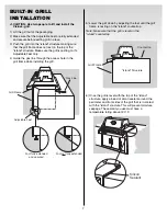
Page 6: ... A 48 inch corrugated gas line is supplied with the grill This line needs to pass through the gas inlet opening to the main gas supply 1 Connect the corregated gas line to the manifold located on the right hand side of grill under the control panel Note Leave an access in the island structure for gas supply and regulator service not inside the grill structure Vieluxe has a gas line and regulator a...

Page 7: ...re the grill is resting on it s Adjustable Feet only 4 Guide the gas line through the access hole in the grill frame while installing the grill Grill Frame Island Structure Countertop 5 Lower the grill down by adjusting the feet until the grill frame is resting on the island countertop Note Make sure that the grill is level on the island countertop 6 Once the grill is level with the top of the isl...

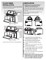
Page 8: ...rom the center outward Locate the vents at both the bottom of the structure and at the top of the structure The bottom vents should be as close to ground level as possible Make sure the vent area is not blocked by interior supports of the structure We recommend vents with screens Access doors to the structure are not considered vents Clean the vents periodically DANGER Failure to follow recommende...

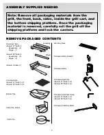
Page 9: ...s removed carefully roll the grill off the shipping platform and lock the casters Bottom Tray Warming Rack Flavorizer Bars Vieluxe 27 Built In Assemblies 2 Single 1 Vieluxe 39 Built In Assemblies 3 Single 2 Assembly Single Catch Pan Holder Rotisserie Motor Bracket Rotisserie Shaft Assembly Rotisserie Split Fork Screw Vieluxe 27 Built In 2 Vieluxe 39 Built In 4 Rotisserie Split Fork Vieluxe 27 Buil...

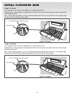
Page 10: ...orizer bar assembly single Flavorizer bar then Flavorizer bar assembly Vieluxe 27 Built In Flavorizer bar Cooking grill support Flavorizer bar Slot Vieluxe 39 Built In Vieluxe 39 Built In Parts required 3 Flavorizer bar assemblies 2 single Flavorizer bars Set the Flavorizer bar assemblies and single Flavorizer bars front to back over the burners in the slots of the Flavorizer bar cooking grill sup...

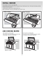
Page 11: ...of the Flavorizer bars Note For directions on how to use the smoker see Installation Guide Vieluxe 27 Built In Vieluxe 39 Built In ADD COOKING GRATES Parts required 2 cooking grates The cross rail of the cooking grate goes down Set the cooking grates in place next to each other Vieluxe 27 Built In Vieluxe 39 Built In Parts required 3 cooking grates The cross rail of the cooking grate goes down Set...

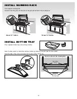
Page 12: ...uxe 27 Built In Vieluxe 39 Built In Mounting Slots Tabs of bottom tray View from front of the Cooking Box INSTALL BOTTOM TRAY Parts required bottom tray and catch pan holder Note It will be easier to install the catch pan holder by removing the catch pan from the holder Hook the tabs of the catch pan holder into the slots of the bottom tray ...

Page 13: ...Slide the bottom tray into the mounting slots under the bottom of the cooking box with the handle of the catch pan toward you CAUTION Do not line the bottom tray with aluminum foil It can cause grease fires by trapping the grease and not allowing grease to flow into the catch pan Vieluxe 39 Built In Vieluxe 27 Built In 2004 Weber Stephen Product Co Vieluxe is a registered U S trademark of Weber St...

Reviews: