Page
3
of
16
Important:
Please note this tool is designed for intermittent subsea use. Please refer to the
manufacturer (Allspeeds Ltd) or an authorized distributor should you wish to use this tool
subsea for any period over 14 days.
CAUTION
– Any modification made to this tool will invalidate the warranty and may lead to
equipment failure or personal injury. If in doubt please contact the manufacturer (Allspeeds Ltd)
or an authorised distributor for assistance.
INSPECT THE TOOL BEFORE USE
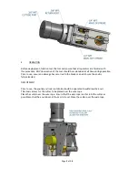
With the cutter isolated from the hydraulic supply, check the condition of the blade edge. If the
blade is damaged or blunt replace with a fresh blade before cutting. This procedure is as
described in section 8.
Ensure that care is taken when checking the blade as the edge may be sharp
Check the condition of the anvil. It is normal that the anvil will show an indent where the blade
has pressed down into it and can withstand multiple cuts, but any excessively damaged anvil
should be replaced. This procedure is as described in section 7
CAUTION – USE OF BLADES AND PARTS NOT APPROVED BY WEBTOOL MAY RESULT IN TOOL
FAILURE AND CONSEQUENTIAL DAMAGE
2.
CUTTING CAPACITY
The cutter is primarily intended for use on steel wire rope, having a maximum tensile strength
of 1880N/mm and will cut ropes up to 155mm diameter. It may be used on alternative
materials, such as electrical power or communication cables, again up to a maximum of 155mm
diameter. Where smaller diameters are to be cut, effort should be made to place the material
centrally along the anvil to minimise any offset loading.
IMPORTANT - Cutting close to the free end of a long wire rope may create unequal loads and
lead to
blade failure
. Ensure that the cutter is placed a minimum of 10 x the rope diameter
along the length of the rope.
For optimal results when cutting short pieces (for example, during cutting trials) locate the
cutter centrally along the length of the rope to equalise loading on the blade.
Failing to follow these instructions may lead to damage of the cutting blade and/or anvil.
3.
INSTALLATION
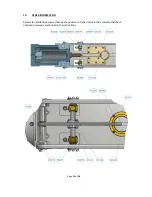
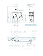
Tapped Holes, ⅝” UNC, are provided in the tool body (see sketch) which can be
used for any attachment necessary to mount the cutter. The cylinder is a pressure vessel and is
not recommended as a mounting point, the cylinder should not be drilled, machined, mutilated
or damaged in any way, any warranty could be invalidated by such actions.


