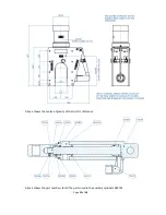
background image

Page 

7

 of 

16


5.


AFTER USE


When  the  tool  is  retrieved,  it  should  be  hosed  off  with  clean  water,  allowed  to  drain  and 
sprayed externally with a de-watering fluid. Before storage, inspect the general condition of the 
tool. Particular attention should be  paid to the anvil and blade. The  anvil should be clean and 
free from any damage or bruising on the outside diameter that would prevent it from retracting 
properly.  The  blade  edge  should  be  smooth  and  free  from  any  serrations.  Note  that  a  slight 
ripple to the blade edge is acceptable and will not cause problems. Any minor damage can be 
smoothed off with an oil stone if necessary. 
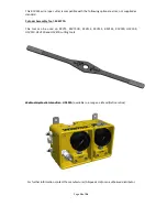
 

6.


SERVICE


It  is  unlikely  that  service  would  be  required  on  the  hydraulic  components  of  the  tool  under 
normal  circumstances,  but  a  seal  spares  kit  is  available  if  required.  The  only  parts  that  would 
need  intermittent  replacement  would  be  the  anvil,  blade  and  wear  plates,  depending  on  the 
frequency of use and materials being cut. These parts can be ordered up on the following spares 
reference numbers, but in addition please quote the tool serial number. 
 
Seal Kit  


Part Number 

995 284 

Anvil 


Part Number 

SSC 6491 

Blade   


Part Number 

705 054C 

Wear plates  


Part number 

765 231A & B    

2 off each  

 
We advise that any servicing should be carried out by an authorised distributor only. 
If required, the tool can be returned to the manufacturer for servicing and testing. 
 
If servicing is to be undertaken by the user, please see note on proof testing under  
SAFETY (Chapter 1), and the following:- 
 
All servicing operations should be carried out in a clean environment to prevent contamination 
of the oil and mating components. 
Care should be taken with all mating areas ie. threads and sealing faces, as any damage or 
abrasive contamination could cause galling or seizing on re-assembly. 
The cylinder is a pressure vessel and should not be drilled, machined, mutilated or damaged in 
any way for mounting purposes or to assist in its removal for servicing, any warranty could be 
invalidated by such actions. 
The use of stilsons to remove the cylinder is not recommended as damage will occur. 


7. 

REPLACEMENT OF THE ANVIL 


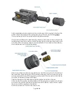
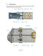
Extend the auxiliary cylinders so that the lever arm 765213exits the anvil guide bush 715354. 
Loosen the 8 off M6 screws 035079 holding pivot pin housings 749045A & B.  
Loosen the M6 retaining screw 035073.  

Summary of Contents for RCV155

Page 1: ...5 5LW Tel 44 0 1254 615100 www allspeeds co uk WIRE ROPE CUTTER RCV155 PRODUCT CODE No 980218 INSTRUCTIONS FOR INSTALLATION OPERATION MAINTENANCE Revision 5 issue 4 Modification No 20691 Date 28th Feb...

Page 2: ...e that suitable pressure regulation equipment is used and that the unit is not subjected to pressures higher than those stated in section 3 In all cases where an operator is present the safety aspects...

Page 3: ...IN TOOL FAILURE AND CONSEQUENTIAL DAMAGE 2 CUTTING CAPACITY The cutter is primarily intended for use on steel wire rope having a maximum tensile strength of 1880N mm and will cut ropes up to 155mm dia...

Page 4: ...els The weight of the tool is 240kg TABLE 1 Function Max Working Pressure Swept Volume Port Tapping psi bar ml U S Gallon Main Ram Working Stroke 10 000 690 2900 0 766 3 8 NPT Main Ram Return Stroke 1...

Page 5: ...no damage has occurred to the blade or anvil Ensure the anvil is fully retracted DEPLOYMENT Prior to use the auxiliary cylinder outstroke should be operated to withdraw the anvil This clears access fo...

Page 6: ...l has a relief valve fitted which will blow off at approx 750 bar DO NOT leave the pressure on so that the relief valve is continually blowing off TROUBLESHOOTING If the wire rope does not cut through...

Page 7: ...he tool serial number Seal Kit Part Number 995 284 Anvil Part Number SSC 6491 Blade Part Number 705 054C Wear plates Part number 765 231A B 2 off each We advise that any servicing should be carried ou...

Page 8: ...e anvil pin 761247 from the anvil SSC6491 The anvil may now be slid out from the anvil guide bush Re assembly is the reverse of the above process 8 REPLACEMENT OF THE CUTTING BLADE First withdraw the...

Page 9: ...entres A cylinder assembly tool is available if required part number SK4377A First remove the anvil as described above in section 7 pump out the ram and remove the blade again as described above in se...

Page 10: ...ld be taken not to disturb the settings When re assembling the relief valve plug with the ram first fill the ram with oil to the bottom of the counterbore smear silver goop on to the threads of the pl...

Page 11: ...Page 11 of 16 10 OTHER INFORMATION Below are detailed two views showing the positions of other items in the assembly than have not been previously mentioned in the instructions...

Page 12: ...Page 12 of 16 Above shows the centre of gravity of the tool for reference Above shows the part numbers for all the parts used in the auxiliary cylinders 982132...

Page 13: ...2 Piston block 2 728078 Cylinder auxiliary 2 SSC6476 Auxiliary end cap 2 764116 Auxiliary piston 2 026701 Pellet 2 043206 Socket set screw M4 x 6 2 035067 Socket cap screw M5 x 30 8 701195 Swagelok co...

Page 14: ...32 Part No Description Qty 709062 Piston block 1 728078 Cylinder 1 SSC6476 End cap 1 764116 Piston 1 026701 Pellet 1 043206 Socket set screw M4 x 6 1 035067 Socket cap screw M5 x 30 4 701195 Swagelok...

Page 15: ...ylinder Assembly Tool SK4377A This tool can be used on RCV75 RCV75HD RCV115 RCV135 RCV155 RCV190 HCV100 HCV120 HCV250 and HCV270 cutting tools Webtool Hydraulic Intensifier HP690A available in a range...

Page 16: ...HCV capable of cutting cable umbilical and armoured flexible pipe lines up to 330mm diameter Softline Cutters SL capable of cutting fibre ropes in various sizes Wire Rope Cable Grippers Wire Rope Clam...

Reviews: