Parts & Service 21/09/2015
902-002-11 Rev 6
Page 7
SECTION 2:
Operation
2.0 TERMINOLOGY
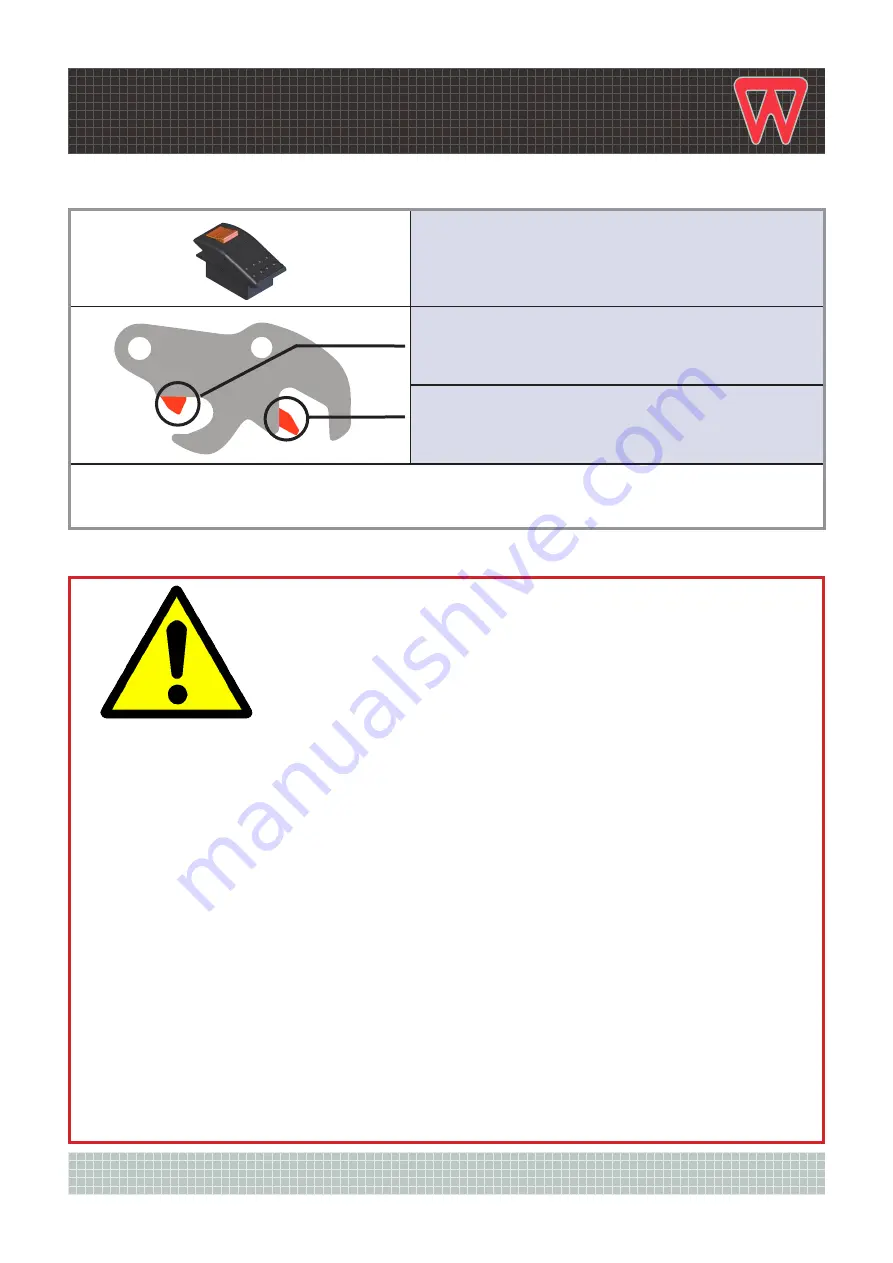
LOCK-OUT SWITCH
KNUCKLE – AT THE FRONT OF THE COUPLER
(CLOSEST TO THE CAB)
WEDGE – AT THE REAR OF THE COUPLER
(FURTHEST FROM THE CAB)
NOTE: The I-Lock Tilt Coupler and I-Lock Standard Coupler operate in the same manner. For clarity
the images of the coupler shown on the following pages are of the Standard I-Lock Coupler.
PLEASE READ CAREFULLY
The automatic resetting of the SAFETY KNUCKLE
during operation is controlled by a “built-in
timer” in the I-Lock controller. This is a safety
feature providing “instant latching” of the first pin.
In the event the safety knuckle “re-sets” to the safe (down)
position before the coupler has been completely moved away
from the attachment, simply crowd the coupler, re-seat the
attachment and re-activate the lock-out switch to raise the
safety knuckle. Only when the safety knuckle is raised can
the coupler be moved away from the attachment.
2.1 SAFETY KNUCKLE FEATURE
NOT TO SCALE


