12
NORTH AMERICA
SECTION 4: HYDRAULIC KIT INSTALLATION
4.4 HOSE ROUTING
Wedgelock Hose Kits have been designed to improve the speed and ease in which an installer
can fit the hydraulic kit. The content of the hydraulic hose kit has been pre determined to ensure
that, in most cases, the majority of fittings required to complete the install are provided. In some
circumstances additional fittings may have to be sourced to complete the connection to the pump
test port and tank return. For information regarding the port type at these locations please refer to
the carrier machine service manual.
The “Pre-Crimped” Wedgelock hose kits are color coded at each end of the pre-crimped hoses.
Following the Installation Reference Card will assist with identifying each of the hoses to be routed
in respect to their relative positions on the carrier machine. Once the Hose Clamp Bracket and
solenoid control valve are in position begin routing the hoses from the coupler end of the machine
to the engine compartment end.
If using a “Pre-Crimped” Hose Kit follow the instructions ensuring that each color coded hose is
positioned as required. If using a ‘Lose Fitting Kit” you can use the color coded instructions as a
guide to achieve the same results.
4.5 HOSE ROUTING – DIPPER ARM
•
Connect the “Dipper Arm” hoses to the coupler cylinder and the safety latch cylinder. These
hoses will be color coded BLUE. Route these hoses through the Hose Clamp Bracket and up
along the upper side of the of the dipper arm.
•
Determine best position for the hose clamps provided. Prepare surface of the dipper arm for
welding the clamps into position. Weld clamp assemblies (if needed) ensuring that only the
vertical ends of the clamp brackets are welded. Touch up paint the dipper arm and clamp to
match the carrier machine color.
•
During clamp welding procedure ensure that the dipper hoses are placed in a clean and safe
position away from heat and the welding area.
•
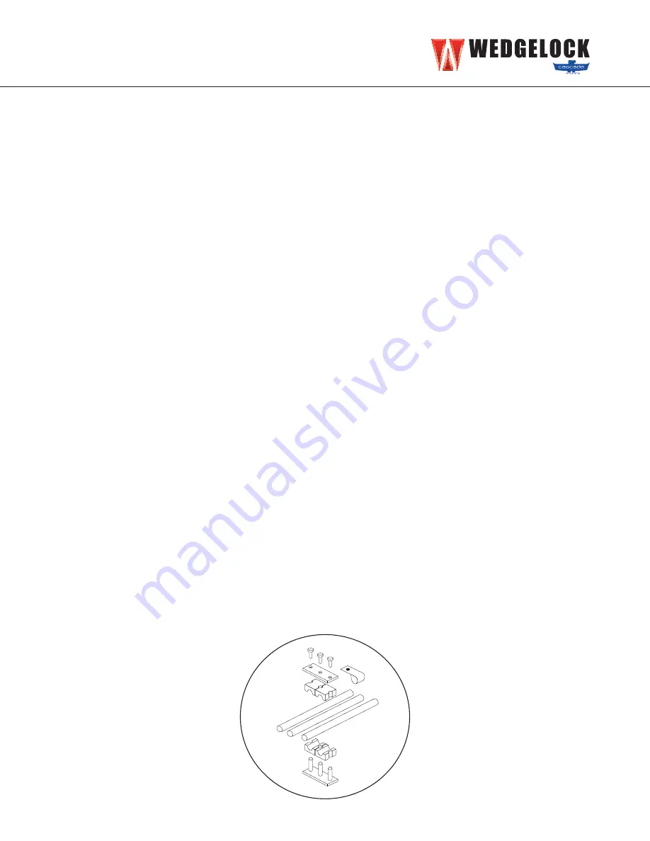
Lightly clamp dipper arm hoses into position, do not fully tighten at this stage. (Fig 4.5.2)
Fig 4.5.2 Hose Clamp Assembly


