background image

4

ASSEMBLY

WARNING:

If received assembled,

review all assembly steps to ensure your unit

is properly assembled and all fasteners are

secure.

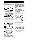
TUBE ASSEMBLY

Wire protector

Upper Locking Sleeve Assembly

Lower Locking Sleeve Assembly

2. Align upper tube groove with triangle on

lower locking sleeve assembly. Push

tubes together until they snap into place.

Alignment Triangle

Upper Tube

Groove

3. Try to pull tubes back apart. If the tubes do

not come apart, they are properly snapped

into place. If the tubes come apart, repeat

step 1 and push until the tubes snap into

place.

4. Slide upper locking sleeve assembly over

lower locking sleeve assembly and tight-

en by turning clockwise.

5. Ensure locking sleeve assembly and

alignment decals appear as illustrated be-

low.

Alignment decals

WARNING:

Failure to completely en-

close excess wires in upper tube during assem-

bly of the unit may result in damage to the wires

and/or the unit or serious injury to the operator

including electrocution.

WARNING:

The upper and lower

tubes must be snapped together, remain per-

manently assembled together and the locking

sleeve assembly must be fully tightened be-

fore and during use to avoid serious injury to

the operator and/or damage to the unit. DO

NOT attempt to disassemble unit after initial

assembly.

INSTALLATION OF ASSIST HANDLE

1. Place unit on a flat surface.

2. Remove knob and bolt from kit.

3. Firmly push the assist handle over the

tube. To make installation easier, tilt han-

dle toward trigger housing while pushing

down (see illustration).

4. Install bolt in handle. Thread knob

onto bolt.

5. Adjust the handle up or down the tube to a

comfortable postion; tighten knob secure-

ly.

ATTACHING EDGE GUIDE AND

SHIELD

WARNING:

The shield must be prop-

erly installed. The shield provides partial

protection from the risk of thrown objects to

the operator and others. Your unit is equipped

with a line limiter blade, which cuts excess

line to the proper length while running. The

line limiter blade (on underside of shield) is

sharp and can cut you.

NOTE:

If shield is not properly installed, dam-

age to unit (including motor failure) will result.
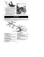
1. Insert edge guide into two holes in shield.

NOTE:

Edge guide

must

be positioned on

shield prior to installation on motor housing

(see following illustration).

Assist handle

Tube

Trigger

housing

Wires

1. Remove the wire protector from the 

tubes and discard.

Summary of Contents for 115254026

Page 1: ...ciones de seguridad Antes de ensamblar el producto lea cuidado samente el instructivo El no hacerlo puede resultar en lesiones gra ves AVERTISSEMENT Veuillez lire le manuel de l utilisateur et bien respecter tous les avertissements et toutes les instructions de sécurité Bien lire les instructions avant d assembler l outil Tout défaut de le faire pourrait entraîner des blessures graves 115254026 24...

Page 2: ...cohol drugs or medication Watch what you are doing use common sense S Avoid unintentional starting of the unit Never carry unit with your finger on the switch Be sure the switch is in the OFF position and never touch the switch when connecting extension cord ELECTRICAL SAFETY WARNING Avoid a dangerous envi ronment To reduce the risk of electrical shock do not use in rain in damp or wet loca tions ...

Page 3: ... it was designed S Use only in daylight or in good artificial light MAINTENANCE SAFETY WARNING Disconnect unit from the power supply before performing mainte nance or when changing trimmer line S Maintain unit according to recommended procedures Keep cutting line at proper length Follow instructions for changing trimmer line S Have all service and maintenance not ex plained in this manual performe...

Page 4: ...d thelocking sleeve assembly must be fully tightened be fore and during use to avoid serious injury to the operator and or damage to the unit DO NOT attempt to disassemble unit after initial assembly INSTALLATION OF ASSIST HANDLE 1 Place unit on a flat surface 2 Remove knob and bolt from kit 3 Firmly push the assist handle over the tube To make installation easier tilt han dle toward trigger housi...

Page 5: ...Limiter Blade Trimmer Head with 0 065 in Trimmer Line RECESSED PLUG The RECESSED PLUG is where you attach your extension cord to the unit TRIGGER SWITCH TheTRIGGER SWITCHis used toturn onthe unit Squeezethetrigger switchto operatethe unit Release to stop LINE LIMITER BLADE The LINE LIMITER BLADE cuts the cutting line to the proper cutting length ASSIST HANDLE The ASSIST HANDLE is used to help hold...

Page 6: ... not crowded into material being cut Cord Retainer Extension Cord AUTOMATIC LINE FEED SYSTEM When the trimmer is initially started a small length of cutting line is fed out After approximately 5 seconds the line will be cut to the correct length by the line limiter as the motor reaches full speed Make sure the motor is up to full speed before trimming If the noise of the cutting line being cut can...

Page 7: ...0 065 inch 1 65 mm diameter line Other sizes of linewill notad vance properly andwill resultin improper cutting head function or can cause serious injury Do not use other materials such as wire string rope etc Wire can break off during cutting and becomea dangerous missile thatcan causese rious injury See page 2 for warning concerning other cutting devices TRIMMING Hold the bottom of the trimmer h...

Page 8: ...move line from notch and feed line through eyelet 12 Reinstall the spool cap MAINTENANCE WARNING Disconnect unit from the power source before performing mainte nance GENERALRECOMMENDATIONS Thewarranty onthis unit does not coveritems that have been subjected to operator abuse or negligence To receive full value from the warranty the operator must maintain unit as instructed in this manual Various a...

Page 9: ...de of head 5 Dirt buildup on unit 1 Crowding trimmer line against material being cut 2 Electrical failure 3 Thrown circuit breaker 4 Debris stopping head Line usage is excessive 1 Check line routing 2 Replace spool 3 Cut with tip of line fully extended 4 Replace spool 1 Line improperly routed in head 2 Line size is incorrect 3 Crowding line against material being cut 4 Spool worn or damaged WARNIN...

Page 10: ...al adjustments explained in the instruction manual Should you have any unanswered questions concerning this warranty please contact WEED EATER a division of Husqvarna Consumer Outdoor Products N A Inc 7349 Statesville Road Charlotte NC 28269 1 800 554 6723 In Canada contact WEED EATER 850 Matheson Blvd West Mississauga Ontario L5V 0B4 Giving the model number serial number and date of purchase of y...

Reviews: