background image

19

SERVICE AND ADJUSTMENTS

CAUTION:  BEFORE PERFORMING ANY SERVICE OR ADJUSTMENTS:

Depress clutch/brake pedal fully and set parking brake.

Place gearshift lever in neutral (N) position.

Place attachment clutch  in “DISENGAGED” position.

Turn ignition key “OFF” and remove key.

Make sure the blades and all moving parts have completely stopped.

Disconnect spark plug wire from spark plug and place wire where it cannot come in contact with
plug.

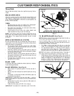
TRACTOR

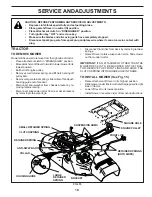
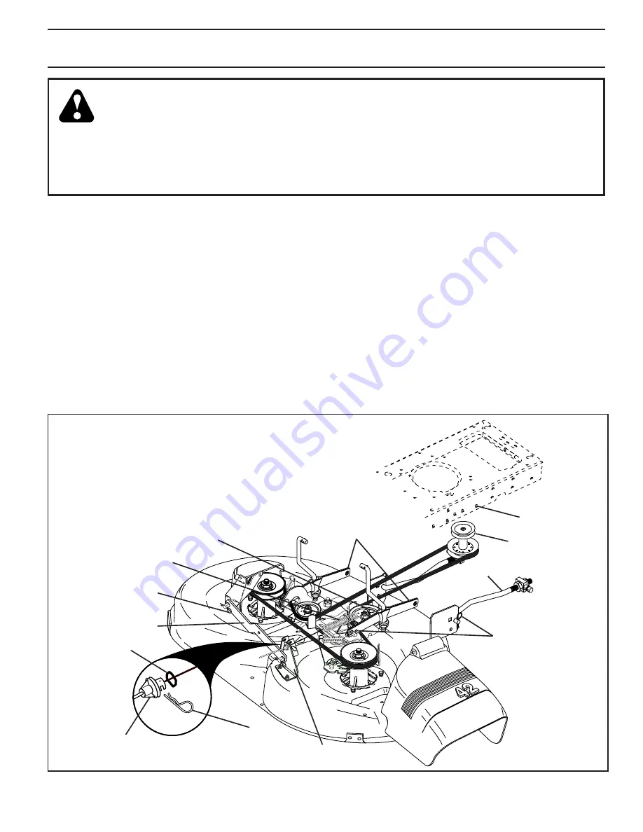
TO REMOVE MOWER

Mower will be easier to remove from the right side of tractor.

Place attachment clutch in “DISENGAGED” position.

Move attachment lift lever forward to lower mower to its
lowest position.

Roll belt off engine pulley.

Remove small retainer spring, and lift clutch spring off
pulley bolt.

Remove large retainer spring, slide collar off and push
housing guide out of bracket.

Disconnect anti-swaybar from chassis bracket by re-
moving retainer spring.

Disconnect suspension arms from rear deck brackets
by removing retainer springs.

Disconnect front links from deck by removing retainer
springs.

Raise lift lever to raise suspension arms. Slide mower
out from under tractor.

IMPORTANT: IF AN ATTACHMENT OTHER THAN THE
MOWER DECK IS TO BE MOUNTED ON THE TRAC-
TOR, REMOVE THE FRONT LINKS AND HOOK THE
CLUTCH SPRING INTO SQUARE HOLE IN FRAME.

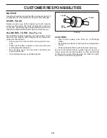
TO INSTALL MOWER (See Fig. 15)

Raise attachment lift lever to its highest position.

Slide mower under tractor with discharge guard to right
side of tractor.

Lower lift lever to its lowest position.

Install mower in reverse order of removal instructions.

SUSPENSION ARMS

RETAINER SPRINGS
(BOTH SIDES)

RETAINER SPRING

ANTI-SWAY BAR

HOUSING GUIDE

FRONT LINK

COLLAR

ENGINE PULLEY

LARGE
RETAINER
SPRING

CLUTCH SPRING

SMALL RETAINER SPRING

BRACKET

SQUARE HOLE

FIG. 15

Summary of Contents for 174193

Page 1: ...ANUAL MODEL NO WE12542F 12 5 HP 42 Inch LawnTractor For Parts and Service contact our authorized distributor call 1 800 849 1297 For Technical Assistance call 1 800 829 5886 174193 1 28 00 RD PRINTED...

Page 2: ...the slope Safe Operation Practices for Ride On Mowers IMPORTANT THIS CUTTING MACHINE IS CAPABLE OF AMPUTATING HANDS AND FEET AND THROWING OBJECTS FAILURE TO OBSERVE THE FOLLOWING SAFETY INSTRUCTIONS...

Page 3: ...Use slow speed Choose a low gear so that you will not have to stop or shift while on the slope Avoid starting or stopping on a slope If tires lose traction disengage the blades and proceed slowly stra...

Page 4: ...ent well trainedtech nicians and the proper tools to service or repair this tractor Please read and retain this manual The instructions will enable you to assemble and maintain your tractor properly A...

Page 5: ...t Washer 1 Locknut 5 16 18 1 Hex Bolt 5 16 18 x 1 1 4 1 Hex Bolt 3 8 16 x 1 1 Lockwasher 3 8 Steering Boot Steering Extension Shaft Steering Wheel Adapter 1 Bolt 1 Washer 17 32 x 1 3 16 x 12 Gauge Sea...

Page 6: ...ghtness FIG 1 BEFORE REMOVING TRACTOR FROM SKID ATTACH STEERING WHEEL See Fig 1 ASSEMBLE EXTENSION SHAFT AND BOOT Slide extension shaft onto lower steering shaft Align mountingholesinextensionandlower...

Page 7: ...tery for minimum of one hour at 6 10 amps See BATTERY inCUSTOMERRESPONSIBILITIES section of this manual for charging instructions FIG 2 BATTERY BOX DOOR SEAT PAN LABEL TERMINAL TERMINAL ADJUSTMENT BOL...

Page 8: ...DECK LEVELNESS For best cutting results mower housing should be properly leveled See TOLEVELMOWERHOUSING intheService and Adjustments section of this manual CHECK FOR PROPER POSITION OF ALL BELTS See...

Page 9: ...RD FAST SLOW ENGINE ON ENGINE OFF OIL PRESSURE LIGHTS ON FUEL CHOKE MOWER HEIGHT PARKING BRAKE LOCKED UNLOCKED REVERSE NEUTRAL HIGH LOW ATTACHMENT CLUTCH ENGAGED MOWER LIFT DANGER KEEP HANDS AND FEET...

Page 10: ...d off THROTTLE CHOKE CONTROL Used for starting and controllingenginespeed CLUTCH BRAKE PEDAL Used for declutching and brak ing the tractor and starting the engine PARKINGBRAKE Locksclutch brakepedalin...

Page 11: ...approximately1 1 2 to 4 The heights are measured from the ground to the blade tip with theenginenotrunning Theseheightsareapproximateand may vary depending upon soil conditions height of grass and typ...

Page 12: ...wait for a few seconds remove and read oil level If necessary add oil until FULL mark on dipstick is reached Do not overfill For cold weather operation you should change oil for easier starting See O...

Page 13: ...of fuel it will take extra cranking time to move fuel from the tank to the engine Sit on seat in operating position depress clutch brake pedal and set parking brake Place gear shift lever in neutral N...

Page 14: ...ery 7 Tighten front axle pivot bolt to 35 ft lbs maximum Do not overtighten 1 12 3 2 5 5 6 7 GENERAL RECOMMENDATIONS The warranty on this tractor does not cover items that have beensubjectedtooperator...

Page 15: ...llel with the ground If blade is balanced it should remain in a horizontal position If either end of the blade moves downward sharpen the heavy end until the blade is balanced TRACTOR Always observe s...

Page 16: ...hten securely Refill engine with oil through oil fill dipstick tube Pour slowly Do not overfill For approximate capacity see PRODUCTSPECIFICATIONS sectionofthismanual Use gauge on oil fill cap dipstic...

Page 17: ...lyonflatsurface Ifvery dirty or damaged replace cartridge Reinstall cartridge nut precleaner cover and secure with knob s IMPORTANT PETROLEUM SOLVENTS SUCH AS KEROSENE ARE NOT TO BE USED TO CLEAN THE...

Page 18: ...o carburetor replacementisrequired With engine cool remove filter and plug fuel line sec tions Place new fuel filter in position in fuel line with arrow pointingtowardscarburetor Be sure there are no...

Page 19: ...slide collar off and push housing guide out of bracket Disconnect anti swaybar from chassis bracket by re movingretainerspring Disconnect suspension arms from rear deck brackets by removing retainer s...

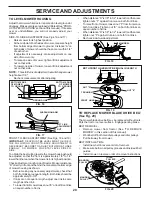
Page 20: ...rightsideoftractor Measuredistance D directly in front and behind the mandrel at bottom edge of mower housing as shown Before making any necessary adjustments check that both front links are equal in...

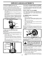
Page 21: ...lock up axle securely Remove axle cover retaining ring and washers to allow wheelremoval rearwheelcontainsasquarekey Donot lose Repair tire and reassemble Onrearwheelsonly aligngroovesinrearwheelhuban...

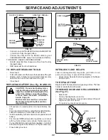
Page 22: ...ully chargedbattery RED cable last from both batteries TO REPLACE HEADLIGHT BULB Raisehood Pullbulbholderoutoftheholeinthebacksideofthegrill Replace bulb in holder and push bulb holder securely back i...

Page 23: ...BE DANGEROUS IF YOU THINK THE ENGINE GOVERNED HIGH SPEED NEEDS ADJUSTING CONTACT YOUR NEAREST AUTHORIZED SERVICE CENTER DEPARTMENT WHICH HAS PROPER EQUIPMENT AND EXPERIENCE TO MAKE ANY NECESSARY ADJU...

Page 24: ...G IN ESSENTIAL FUEL SYSTEM PARTS SUCH AS CARBURETOR FUEL FILTER FUEL HOSE OR TANK DURING STORAGE ALSO EXPERIENCE INDICATES THAT ALCOHOL BLENDED FUELS CALLED GASOHOL OR USING ETHANOL OR METHANOL CAN AT...

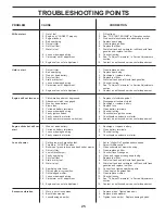
Page 25: ...ty ignition switch 7 Check replace ignition switch 8 Faulty solenoid or starter 8 Check replace solenoid or starter 9 Faulty operator presence switch es 9 Contact an authorized service center departme...

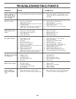
Page 26: ...mowing 4 Mower deck not level 4 Level mower deck 5 Low uneven tire air pressure 5 Check tires for proper air pressure 6 Worn bent or loose blade 6 Replace sharpen blade Tighten blade bolt 7 Buildup o...

Page 27: ...R TRACTOR IS EQUIPPED WITH A SPECIAL ALTERNATOR SYSTEM THE LIGHTS ARE NOT CONNECTED TO THE BATTERY BUT HAVE THEIR OWN ELECTRICAL SOURCE BECAUSE OF THIS THE BRIGHTNESS OF THE LIGHTS WILL CHANGE WITH EN...

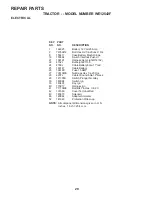
Page 28: ...28 28 29 26 24 42 43 27 27 25 41 27 27 40 33 30 8 2 1 27 48 16 16 22 21 REPAIR PARTS TRACTOR MODEL NUMBER WE12542F ELECTRICAL 52...

Page 29: ...66180 Fuse 15 AMP 27 73510400 Nut Keps Hex 1 4 20 Unc 28 4207J Cable Ground 6 Ga 12 black 29 121305X Switch Plunger Nc Gray 30 163968 Switch Ign 33 140401 Key Ign 40 170217 HarnessIgn 41 71110408 Bolt...

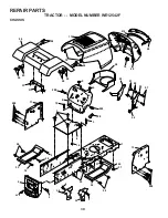
Page 30: ...R PARTS TRACTOR MODEL NUMBER WE12542F CHASSIS 3 2 35 3 26 35 3 26 33 10 34 1 208 11 17 29 28 208 13 12 51 57 53 52 54 55 24 26 25 26 25 3 31 24 30 3 8 3 6 16 9 15 209 209 5 5 58 145 37 37 18 206 3 3 3...

Page 31: ...Gr 5 25 19131312 Washer 13 32 X 13 16 X 12 Ga 26 73800600 Nut Lock Hex w Ins 3 8 16 Unc 28 140434 Grille Lens Asm 29 140273X599 Lens Grille Private Label 30 169465X550 Fender 31 136619 Bracket Fender...

Page 32: ...14 41 42 40 38 42 39 57 51 42 51 74 75 78 76 77 25 19 24 2 53 35 34 37 36 35 62 36 64 65 59 56 51 72 55 63 116 70 77 61 22 27 26 6 113 18 51 5 18 6 52 30 32 32 30 52 11 204 170 21 4 3 13 10 8 12 12 7...

Page 33: ...4 Gr 5 40 4470J Spacer Split 395 X 59 Bzp 41 165838 Keeper Belt Idler 42 19131312 Washer 13 32 X 13 16 X 12 Ga 47 127783 Pulley Idler V Groove Plastic 48 154407 Bellcrank Clutch Grnd Drv STL 49 123205...

Page 34: ...4 3 32 43 6 43 8 18 19 22 27 23 40 66 29 25 79 8 10 40 11 8 6 9 46 46 8 6 9 2 47 47 17 26 30 28 1 41 42 37 36 37 38 63 11 39 11 80 68 67 67 67 13 65 85 85 68 15 15 15 29 29 82 REPAIR PARTS TRACTOR MOD...

Page 35: ...ire Form 19 75 Mech 36 155099 Bushing Strg 5 8 Id Dash 37 152927 Screw 38 140045 Cap Wheel Steer Ayp 39 19133812 Washer 13 32 x 2 3 8 x 12 Ga 40 7810H Nut Lock Center 3 8 24un 41 100711L Adaptor Wheel...

Page 36: ...36 2 1 OPTIONAL EQUIPMENT Spark Arrester 29 44 46 32 31 33 37 33 40 62 13 4 72 78 81 3 14 38 15 16 78 23 45 REPAIR PARTS TRACTOR MODEL NUMBER WE12542F ENGINE...

Page 37: ...Spark Arrestor Flat Scrn 31 109202X Tank Fuel Front 32 140527 Cap Asm Fuel 33 123487X ClampHose 37 137040 Line Fuel 20 38 Oil Drain Plug Order From Engine Manufacturer 40 124028X Bushing Snap Nyl Blk...

Page 38: ...6X Bracket Pnt Mounting Switch 13 121248X Bushing Snap Blk Nyl KEY PART NO NO DESCRIPTION 14 72050412 Bolt Rdhd Sht Nk 1 4 20 X 1 1 2 15 134300 Spacer Split 28 X 96 16 121250X SpringCprsn 17 123976X N...

Page 39: ...38311 Decal Handle Lft Height Adj 174193 Manual Owner sEnglish 174194 Manual Owner sFrench Available accessories not included with mower C42 GrassCatcher MK42 Mulch Kit w Blades KEY PART NO NO DESCRIP...

Page 40: ...40 REPAIR PARTS TRACTOR MODEL NUMBER WE12542F MOWER LIFT 15 20 16 1718 20 20 15 20 4 5 6 2 3 1 6 5 4 7 8 12 11 31 32 31 32 19 19 13 13 13 13...

Page 41: ...e Matte Blk 8 124526X Button Plunger Black 11 139865 Link Lift LH Fixed Length 12 139866 Link Lift RH Fixed Length 13 4939M RetainerSpring 15 173288 Link Front 16 73350800 Nut Jam Hex 1 2 13 Unc 17 13...

Page 42: ...5 14 12 128 13 11 10 9 8 16 68 37 30 31 32 33 146 148 145 150 45 144 147 147 142 149 142 35 49 50 51 54 52 53 55 56 34 1 46 44 21 22 24 25 26 27 2 28 29 23 21 21 21 18 18 20 2 48 59 19 4 3 5 6 21 40 1...

Page 43: ...33835 Fastener Christmas Tree 36 131494 Pulley Idler Flat 37 19131316 Washer 13 32 x 13 16 x 16 Gauge 40 73680600 Nut 44 140088 Guard Mandrel LH 45 4497H Retainer 46 137729 Screw Thdrol 1 4 20 x 5 8 T...

Page 44: ...44 SERVICE NOTES...

Page 45: ...ed for rental or commercial purposes is limited to 90 days from the date of original purchase 5 This Warranty applies only to products which have been properly assembled adjusted operated and maintain...

Page 46: ...f the Power Train Component and parts The cost of normal maintenance and replacement of service items which are not defective shall be paid for by the original purchaser C Securing Warranty Service Wa...

Page 47: ...DE ONLY RIDE UP AND DOWN HILL NOT ACROSS HILL SUGGESTED GUIDE FOR SIGHTING SLOPES FOR SAFE OPERATION Operate your Tractor up and down the face of slopes not greater than 15 never across the face Make...

Page 48: ......
Reviews: