background image

18

SERVICE AND ADJUSTMENTS

WARNING: TO  AVOID  SE RI OUS IN 

JU RY, BEFORE PERFORMING ANY SERVICE OR ADJUST-

MENTS:


Depress clutch/brake pedal fully and set parking brake.


Place gearshift lever in neutral (N) position.


Place attachment clutch  in “DISENGAGED” position.


Turn ignition key to  “STOP” and remove key.


Make sure the blades and all moving parts have completely stopped.


Disconnect spark plug wire from spark plug and place wire where it cannot come in contact  

 with 

plug.

TRACTOR

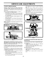
TO REMOVE MOWER (See Fig. 13)

Mower will be easier to remove from the right side of trac-
tor.
•      Place attachment clutch in “DIS EN GAGED” position.
•     Move attachment lift lever forward to low er mower to 

its lowest po si tion.

•      Roll belt off engine pulley.
•         Remove small retainer spring, and remove clutch spring 

off pulley bolt.

•      Remove large retainer spring, slide col lar off and push 

housing guide out of brack et.

•      Disconnect anti-swaybar from chas sis bracket by re-

mov ing re tain er spring.

•      Disconnect suspension arms from rear deck brackets 

by removing retainer springs.

•      Disconnect front links from deck by re mov ing retainer 

springs.

•      Raise lift lever to raise suspension arms. Slide mower 

out from under tractor.

IMPORTANT:

 IF AN ATTACHMENT OTHER THAN THE MOWER 

DECK IS TO BE MOUNTED ON THE TRAC TOR, REMOVE THE 
FRONT LINKS AND HOOK THE CLUTCH SPRING INTO SQUARE 
HOLE IN FRAME.

TO INSTALL MOWER (See Fig. 13)

•      Raise attachment lift lever to its high est position.
•      Slide mower under tractor with defl ector shield to right 

side of tractor.

•      Lower lift lever to its lowest po si tion.
•     Connect front links to mower deck and secure with 

retainer springs..

•     Connect suspension arms to rear deck brackets and 

secure with retainer springs.

•     Connect anti-swaybar to chassis bracket and secure 

with retainer spring.

•         Push clutch cable housing guide into bracket, slide col-

lar onto guide and secure with large retainer spring.

•      Place fl at washer and clutch spring on idler pulley bolt 

and secure with small retainer spring.

•      Install belt onto engine pulley.

SUSPENSION
ARMS

RETAINER SPRINGS
(BOTH SIDES)

RETAINER SPRING

ANTI-SWAY BAR

HOUSING GUIDE

FRONT LINK

COLLAR

ENGINE PULLEY

LARGE 
RETAINER 
SPRING

CLUTCH SPRING

SMALL RETAINER SPRING

BRACKET

SQUARE HOLE

FIG. 13

DEFLECTOR SHIELD

SMALL RETAINER SPRING

CLUTCH SPRING

FLAT WASHER

Summary of Contents for 188313

Page 1: ...DEL NO WET2242STC 22 0 HP 42 Inch Lawn Tractor 188313 6 5 03 MH PRINTED IN U S A For Parts and Service contact our authorized distributor call 1 800 849 1297 For Technical Assistance call 1 800 829 58...

Page 2: ...e manual and on the machine before starting Only allow responsible adults who are familiar with the instructions to operate the machine Clear the area of objects such as rocks toys wire etc which coul...

Page 3: ...he watchful care of another responsible adult Be alert and turn machine off if children enter the area Before and when backing look behind and down for small children Mow up and down slopes 15 Max not...

Page 4: ...for and using your tractor Follow the instructions under Maintenance and Stor age sections of this owner s manual WARNING This tractor is equipped with an internal com bustion engine and should not b...

Page 5: ...pe Sheet 1 Oil Drain Tube 1 Bolt 1 Washer 17 32 x 1 3 16 x 12 Gauge 1 Lock Washer 1 2 1 Large Flat Washer 1 Hex Bolt 1 4 28 x 1 1 4 1 Locknut 1 4 28 1 Locknut 1 2 20 2 Keys Steering Wheel Adapter Stee...

Page 6: ...ER STEERING SHAFT STEERING BOOT EXTENSION SHAFT 1 4 HEX BOLT STEERING WHEEL INSERT ADAPTER 1 2 HEX NUT LARGE FLAT WASHER TABS TAB SLOTS BEFORE REMOVING TRACTOR FROM SKID ATTACH STEERING WHEEL See Fig...

Page 7: ...shift lever in neutral position Turn ignition key to OFF position Continue with the instructions that follow FIG 3 CHECK BATTERY See Fig 3 Lift seat pan to raised position If this battery is put into...

Page 8: ...E FOLLOWING IMPORTANT ITEMS Engine oil is at proper level Fuel tank is filled with fresh clean regular unleaded gasoline Become familiar with all controls their location and function Operate them befo...

Page 9: ...ould result in serious injury or death The safety alert symbol is used to identify safety inform ation about hazards which can result in death serious injury and or property damage DANGER indicates a...

Page 10: ...g and brak ing the tractor and starting the engine PARKING BRAKE Locks clutch brake pedal into the brake position GEARSHIFT LEVER Selects the speed and direction of the tractor ATTACHMENT LIFT LEVER U...

Page 11: ...tion key to OFF position and remove key Always remove key when leaving tractor to prevent unauthorized use Never use choke to stop engine IMPORTANT LEAVING THE IGNITION SWITCH IN ANY POSITION OTHER TH...

Page 12: ...be sure gearshift lever is in neutral N position Do not push or tow tractor at more than five 5 MPH NOTE To protect hood from damage when transporting your tractor on a truck or a trailer be sure hood...

Page 13: ...ts section of this manual CAUTION Alcohol blended fuels called gasohol or using ethanol or methanol can at tract moisture which leads to separation and formation of acids during storage Acidic gas can...

Page 14: ...2 GENERAL RECOMMENDATIONS The warranty on this tractor does not cover items that have beensubjectedtooperatorabuseornegligence Toreceive full value from the warranty operator must maintain tractor as...

Page 15: ...ning and the attachment clutch is engaged any attempt by the operator to leave the seat should shut off the engine The attachment clutch should never operate unless the operator is in the seat BLADE C...

Page 16: ...tightened securely for accurate reading Keep oil at FULL line on dipstick YELLOW CAP ENGINE LUBRICATION Only use high quality detergent oil rated with API service classification SF SJ Select the oil...

Page 17: ...should be replaced once each season If fuel filter becomes clogged obstructing fuel flow to carburetor replacement is required With engine cool remove filter and plug fuel line sec tions Place new fu...

Page 18: ...s Disconnect front links from deck by removing retainer springs Raise lift lever to raise suspension arms Slide mower out from under tractor IMPORTANT IFANATTACHMENTOTHERTHANTHEMOWER DECK IS TO BE MOU...

Page 19: ...equal number of turns FIG 17 BOTH FRONT LINKS MUST BE EQUAL IN LENGTH FIG 16 TO LEVEL MOWER HOUSING Adjust the mower while tractor is parked on level ground or driveway Make sure tires are properly i...

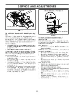
Page 20: ...LER PULLEYS MANDREL PULLEYS 1 1 2 JAM NUT WITH PARKING BRAKE ENGAGED OPERATING ARM NUT A FIG 19 TO CHECK AND ADJUST BRAKE See Fig 19 Your tractor is equipped with an adjustable brake system which is m...

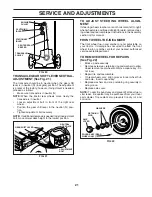
Page 21: ...ering wheel crossbars are not horizontal left to right whenwheelsarepositionedstraightforward removesteer ing wheel and reassemble per instructions in the Assembly section of this manual FRONT WHEEL T...

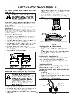
Page 22: ...g care not to short against tractor chassis ConnectoneendoftheBLACKcabletotheNEGATIVE terminal C of fully charged battery Connect the other end of the BLACK cable D to good chassis ground away from fu...

Page 23: ...ee engine manual TO ADJUST CHOKE CONTROL The choke control has been preset at the factory and ad justment should not be necessary If adjustment is neces sary see engne manual TO ADJUST CARBURETOR Your...

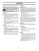
Page 24: ...L FUEL SYSTEM PARTS SUCH AS CARBURETOR FUEL FILTER FUEL HOSE OR TANK DURING STORAGE ALSO EXPERIENCE INDICATES THAT ALCOHOL BLENDED FUELS CALLED GASOHOL OR USING ETHANOLORMETHANOL CANATTRACTMOISTUREWHI...

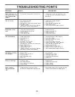
Page 25: ...ty ignition switch 7 Check replace ignition switch 8 Faulty solenoid or starter 8 Check replace solenoid or starter 9 Faulty operator presence switch es 9 Contact an authorized service center departme...

Page 26: ...Mower deck not level 4 Level mower deck 5 Low uneven tire air pressure 5 Check tires for proper air pressure 6 Worn bent or loose blade 6 Replace sharpen blade Tighten blade bolt 7 Buildup of grass le...

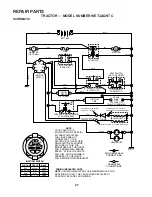
Page 27: ...OTE YOUR TRACTOR IS EQUIPPED WITH A SPECIAL ALTERNATOR SYSTEM THE LIGHTS ARE NOT CONNECTED TO THE BATTERY BUT HAVE THEIR OWN ELECTRICAL SOURCE BECAUSE OF THIS THE BRIGHTNESS OF THE LIGHTS WILL CHANGE...

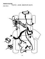
Page 28: ...28 REPAIR PARTS TRACTOR MODEL NUMBER WET2242STC ELECTRICAL 28 29 26 24 42 43 27 27 25 41 27 27 40 33 90 30 8 2 1 27 16 16 52 48 22 21...

Page 29: ...147 Cable Battery 6 Ga w 16 wire red 26 175158 Fuse 20 AMP 27 73510400 Nut Keps Hex 1 4 20 unc 28 4207J Cable Ground 6 Ga 12 black 29 121305X Switch Plunger Nc Gray 30 175566 Switch Ign 33 140401 Key...

Page 30: ...42STC CHASSIS AND ENCLOSURES 26 25 58 64 208 13 208 11 1 3 2 9 208 209 209 209 5 5 207 3 3 3 142 3 3 3 142 17 29 28 12 51 57 53 52 54 55 145 37 3 37 24 26 25 31 24 30 35 3 26 33 10 26 34 35 18 14 38 1...

Page 31: ...der 33 179716X550 Footrest Pnt Lh 34 179717X550 Footrest Pnt Rh 35 72110606 Bolt Rdhd Sht Sqnk 3 8 16 x 3 4 37 17490508 Screw Thdrol 6 16 18 x 1 2 TYT 38 175710 Bracket Asm Pivot Mower Rear 51 7380040...

Page 32: ...78 76 77 1 25 19 24 2 53 35 34 37 36 35 62 36 59 212 55 77 61 22 27 26 6 113 18 51 5 18 6 85 52 30 32 32 30 52 11 85 80 4 3 13 81 84 82 64 65 145 79 16 96 26 27 51 48 150 151 202 49 47 50 120 21 8 10...

Page 33: ...60620 Screw 3 8 16 x 1 1 4 57 130801 V Belt Ground Drive 95 25 59 169691 Keeper Belt Span Ctr 61 17120614 Screw 3 8 16 x 875 62 8883R Cover Pedal Blk Round 63 175410 Engine Pulley 64 71170764 Bolt Hex...

Page 34: ...ACTOR MODEL NUMBER WET2242STC STEERING ASSEMBLY 44 51 54 5 9 5 7 7 9 4 3 32 43 6 43 8 10 40 11 8 6 9 46 46 8 6 9 2 47 47 26 30 28 1 41 42 37 36 37 38 12 39 68 67 67 67 13 65 85 85 68 15 15 15 29 29 82...

Page 35: ...020412 Pin 32 130465 Rod Tie Wire Form 19 75 Mech 36 155099 Bushing Strg 5 8 Id Dash 37 152927 Screw TT 10 32 x 5 x 3 8 Flange 38 140045X428 Insert Cap Strg 39 19183812 Washer 9 16 ID x 2 3 8 OD 12 Gr...

Page 36: ...36 REPAIR PARTS TRACTOR MODEL NUMBER WET2242STC ENGINE 2 1 OPTIONAL EQUIPMENT Spark Arrester 29 26 25 4 23 45 8 10 62 6 5 72 13 14 38 105 16 105 3 81 engine tecumseh_16 33 37 33 44 46 32 31 41 112 40...

Page 37: ...6 11050600 Washer Lock Ext Tooth 3 8 23 169837 Shield Browning Debris Guard 25 161729 Control Choke 26 73920600 Nut Keps 3 8 24 Unf 29 137180 Arrestor Spark 31 180645 Tank Fuel 32 140527 Cap Asm Fuel...

Page 38: ...Washer 17 32 x 1 3 16 x 12 Ga 25 127018X Bolt Shoulder 5 16 18 x 62 26 10040800 Lockwasher 26 23 1 24 16 15 12 13 17 25 4 3 8 9 7 8 9 7 2 6 22 21 5 10 5 14 1 140116 Seat 2 140551 Bracket Pnt Pivot Sea...

Page 39: ...106268X Tire R Ts 18x9 5 8 Service 10 7152J Tube Rear Service Item Only 11 104757X428 Cap Axle 1 50 X 1 00 144334 Sealant Tire 10 oz Tube NOTE All component dimensions given in U S inches 1 inch 25 4...

Page 40: ...40 REPAIR PARTS TRACTOR MODEL NUMBER WET2242STC MOWER LIFT 15 20 16 1718 20 20 15 20 4 5 6 2 3 1 6 5 4 7 8 12 11 31 32 31 32 19 19 13 13 13 13...

Page 41: ...Grip Handle 8 124526X Button Plunger 11 139865 Link Lift Lh 12 139866 Link Lift Rh 13 4939M Retainer Spring 15 173288 Link Front 16 73350800 Nut Jam Hex 1 2 13 Unc 17 175689 Trunnion Blk Zinc 18 7380...

Page 42: ...5 14 13 11 10 9 8 16 68 37 184 30 31 32 33 146 148 145 150 45 144 147 147 142 149 142 54 52 53 55 56 34 1 46 44 21 24 25 26 27 2 28 29 23 21 21 21 18 18 20 2 48 59 19 4 3 5 6 21 40 143 36 40 37 40 159...

Page 43: ...Toplock 9 16 Flange 34 72110614 Bolt 36 131494 Pulley Idler Flat 37 19131316 Washer 13 32 x 13 16 x 16 Ga 40 73680600 Nut 44 140088 Guard Mandrel LH 45 4497H Retainer 46 137729 Screw Thdrol 1 4 20 x 5...

Page 44: ...44 SERVICE NOTES...

Page 45: ...for rental or commercial purposes is limited to 90 days from the date of original purchase 5 This Warranty applies only to products which have been properly assembled adjusted operated and main taine...

Page 46: ...of the Power Train Component and parts The cost of normal maintenance and replacement of service items which are not defective shall be paid for by the original purchaser C Securing Warranty Service...

Page 47: ...he face Do not mow slopes greater than 15 degrees Make turns gradually to prevent tipping or loss of control Exercise extreme caution when changing direction on slopes 1 Fold this page along dotted li...

Page 48: ......
Reviews: