background image

20

SERVICE AND ADJUSTMENTS

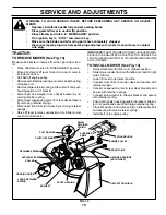
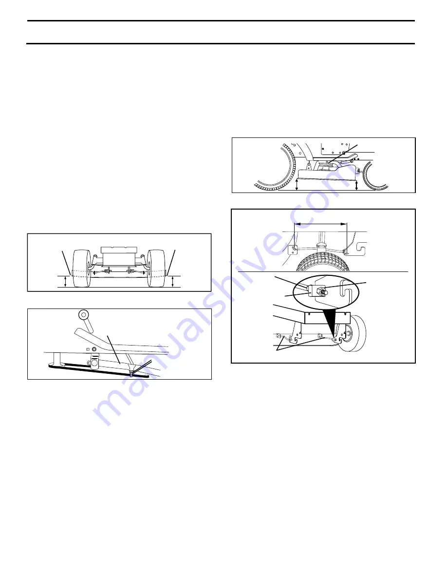
FRONT-TO-BACK ADJUSTMENT (See Figs. 16 and 17) 

IMPORTANT:

  DECK MUST BE LEVEL SIDE-TO-SIDE. IF THE 

FOLLOWING FRONT-TO-BACK ADJUSTMENT IS NECESSARY, 
BE SURE TO AD JUST BOTH FRONT LINKS  EQUAL LY  SO 


MOWER  WILL STAY LEVEL SIDE-TO-SIDE.     


To obtain the best cutting results, the mower housing 
should be adjusted so that the front is approximately 1/8" 
to 1/2" lower than the rear when the mower is in its high-
est position.

Check adjustment on right side of tractor.  Measure dis tance 
“D” directly in front and behind the mandrel at bottom edge 
of mower housing as shown.
•      Before making any necessary adjustments, check that 

both front links are equal in length.  

•      If links are not equal in length, adjust one link to same 

length as other link.

•     To lower front of mower loosen nut “E” on both front 

links an equal number of turns.

FIG. 17

BOTH FRONT LINKS MUST BE EQUAL IN LENGTH

FIG. 16

TO LEVEL MOWER HOUSING

Adjust the mower while tractor is parked on level ground 
or driveway.  Make sure tires are properly infl ated (See 
“PROD UCT SPECIFICATIONS” section of this manual).   If 
tires are over or underinfl ated, you will not properly adjust 
your mower.

SIDE-TO-SIDE ADJUSTMENT (See Figs. 14 and 15)
•      Raise mower to its highest position.
•         At the midpoint of both sides of mower, measure height 

from bot tom edge of mower to ground.   Distance “A” 
on both sides of mower should be the same or within 
1/4" of each other.

•     If adjustment is necessary, make adjustment on one 

side of mower only.

•      To raise one side of mower, tighten lift link ad just ment 

nut on that side.

•      To lower one side of mower, loosen lift link ad just ment 

nut on that side.

NOTE

:  Each full turn of adjustment nut will change mow er 

height about 1/8".
•      Recheck measurements after adjusting.

BOTTOM EDGE 
OF MOWER TO 
GROUND

FIG. 14

FIG. 15

A

A

GROUND LINE

BOTTOM EDGE 

OF MOWER TO 

GROUND

•     When distance “D” is 1/8" to 1/2" lower at front than 

rear, tighten nuts “F” against trunnion on both front 
links.

•      To raise front of mower, loosen nut “F” from trunnion on 

both front links. Tighten nut “E” on both front links an 
equal number of turns. The two front links must remain 
equal in length.

•         When distance “D” is 1/8" to 1/2" lower at front than rear, 

tighten nut “F” against trunnion on both front links.

•      Recheck side-to-side adjustment.

SUS PEN SION ARM

LIFT LINK 
ADJUSTMENT NUT

“D”

“D”

MAN DREL

NUT “E”

TRUNNION

NUT “F”

FRONT LINKS

TO REPLACE MOWER BLADE DRIVE BELT 
(See Fig. 18)

The mower blade drive belt may be replaced without tools.  
Park the tractor on level surface.  Engage parking brake.  

BELT REMOVAL -
•      Place attachment clutch in “DISENGAGED” po si tion.
•      Move at tach ment lift lever forward to lower mower to 

its lowest position.

•      Roll belt off engine pulley.
•         Disconnect R.H. suspension arm from rear deck brack et 

by removing retainer spring.

•      Work belt off both mandrel pulleys and idler pulleys.
•      Pull belt away from mower. 

BELT INSTALLATION -
•      Work new belt around both mandrel pulleys and idler 

pulleys.

•      Install new belt into engine pulley groove.
       Reconnect R.H. suspension arm and secure with re-

 tain er spring.

•      Make sure belt is in all pulley grooves and in side all 

belt guides.

Summary of Contents for 195383

Page 1: ...PROTECTION DURING OPERATION Visit our website www weedeater com WARNING Read this Manual and follow allWarnings and Safety Instructions Failure to do so can result in serious injury IMPORTANT MANUAL...

Page 2: ...parking brake stop engine and remove keys before dismounting Disengage blades when not mowing Shut off engine and wait for all parts to come to a complete stop before cleaning the machine removing the...

Page 3: ...towed equipment except at the hitch point Follow the manufacturer s recommendation for weight limits for towed equipment and towing on slopes Never allow children or others in or on towed equip ment...

Page 4: ...maintaining caring for and using your tractor Follow the instructions under Maintenance and Stor age sections of this owner s manual WARNING This tractor is equipped with an internal com bustion engi...

Page 5: ...ring Wheel Insert 1 Large Flat Washer Steering Boot Steering Wheel Adapter Seat 2 Keys Slope Sheet Key 1 Oil Drain Tube 1 Hex Bolt 5 16 18 x 4 1 5 16 Lock Washer Steering Extension Shaft 1 Bolt 1 Wash...

Page 6: ...slide adapter onto steering shaft extension Position steering wheel so cross bars are horizontal left to right and slide inside boot and onto adapter Assemble large flat washer 5 16 lock washer 5 16...

Page 7: ...rake Place gear shift lever in neutral N position Press lift lever plunger and raise attachment lift lever to its highest position Starttheengine Afterenginehasstarted movethrottle control to idle pos...

Page 8: ...DUCT PLEASE REVIEW THE FOLLOWING CHECKLIST All assembly instructions have been completed No remaining loose parts in carton Battery is properly prepared and charged Minimum 1 hour at 6 amps Seat is ad...

Page 9: ...injury or death The safety alert symbol is used to identify safety inform ation about hazards which can result in death serious injury and or property damage DANGER indicates a hazard which if not av...

Page 10: ...elects the speed and direction of the tractor IGNITION SWITCH Used for starting and stopping the engine Our tractors conform to the safety standards of the American National Standards Institute FIG 4...

Page 11: ...Turn ignition key to OFF position and remove key Always remove key when leaving tractor to prevent unauthorized use Never use choke to stop engine IMPORTANT LEAVING THE IGNITION SWITCH IN ANY POSITION...

Page 12: ...WER See Fig 6 Your tractor is equipped with an operator presence sensing switch Any attempt by the operator to leave the seat with the engine running and the attachment clutch engaged will shut off th...

Page 13: ...ine performance See TO ADJUST CARBURETOR in the Service and Adjustments section of this manual ADD GASOLINE Fill fuel tank to bottom of filler neck Do not overfill Use fresh clean regular unleaded gas...

Page 14: ...e opposite direction making left hand turns until finished See Fig 7 FIG 7 If grass is extremely tall it should be mowed twice to reduce load and possible fire hazard from dried clip pings Make first...

Page 15: ...ng under a heavy load or in high ambient temperatures 2 Service more often when operating in dirty or dusty conditions E N G I N E Replace Oil Filter If equipped Check Transaxle Cooling Check V Belts...

Page 16: ...IFICATIONS section of this manual Keep tires free of gasoline oil or insect control chemi cals which can harm rubber Avoid stumps stones deep ruts sharp objects and other hazards that may cause tire d...

Page 17: ...ll the drain tube onto the fitting Unlock drain valve by pushing inward and turning counterclockwise To open pull out on the drain valve After oil has drained completely close and lock the drain valve...

Page 18: ...fuel line sec tions Place new fuel filter in position in fuel line with arrow pointing towards carburetor Be sure there are no fuel line leaks and clamps are properly positioned Immediately wipe up a...

Page 19: ...rings Disconnect front links from deck by removing retainer springs Raise lift lever to raise suspension arms Slide mower out from under tractor IMPORTANT IFANATTACHMENTOTHERTHANTHEMOWER DECK IS TO BE...

Page 20: ...justment on one side of mower only To raise one side of mower tighten lift link adjustment nut on that side To lower one side of mower loosen lift link adjustment nut on that side NOTE Each full turn...

Page 21: ...19 TO CHECK AND ADJUST BRAKE See Fig 19 Your tractor is equipped with an adjustable brake system which is mounted on the right side of the transaxle If tractor requires more than five 5 feet to stop a...

Page 22: ...ye protection when around batteries If your battery is too weak to start the engine it should be recharged See BATTERY in the Maintenance section of this manual If jumper cables are used for emergency...

Page 23: ...ose hood INTERLOCKS AND RELAYS Loose or damaged wiring may cause your tractor to run poorly stop running or prevent it from starting Check wiring See electrical wiring diagram in the Repair Parts sect...

Page 24: ...UEL SYSTEM PARTS SUCH AS CARBURETOR FUEL FILTER FUEL HOSE OR TANK DURING STORAGE ALSO EXPERIENCE INDICATES THAT ALCOHOL BLENDED FUELS CALLED GASOHOL OR USING ETHANOLORMETHANOL CANATTRACTMOISTUREWHICH...

Page 25: ...aulty ignition switch 7 Check replace ignition switch 8 Faulty solenoid or starter 8 Check replace solenoid or starter 9 Faulty operator presence switch es 9 Contact an authorized service center depar...

Page 26: ...l speed too fast 2 Shift to slower speed 3 Wet grass 3 Allow grass to dry before mowing 4 Mower deck not level 4 Level mower deck 5 Low uneven tire air pressure 5 Check tires for proper air pressure 6...

Page 27: ...sed for rental or commercial purposes is limited to 90 days from the date of original purchase 5 This Warranty applies only to products which have been properly assembled adjusted operated and maintai...

Page 28: ...f the Power Train Component and parts The cost of normal maintenance and replacement of service items which are not defective shall be paid for by the original purchaser C Securing Warranty Service Wa...

Page 29: ...he face Do not mow slopes greater than 15 degrees Make turns gradually to prevent tipping or loss of control Exercise extreme caution when changing direction on slopes 1 Fold this page along dotted li...

Page 30: ...on of part For Techical Assistance call 1 800 829 5886 For a Parts Manual go to our website www weedeater com support asp NOTE Electrolux Home Products provides parts and service through its authorize...

Reviews: