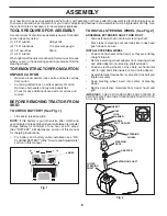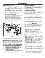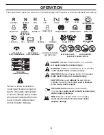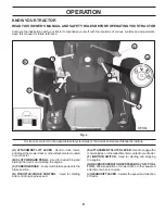
background image

20

SERVICE AND ADJUSTMENTS

•  If adjustment is necessary, see step in Visual Adjust-

ment instructions above.

• 

Recheck measurements, adjust if necessary until both 

sides are equal.

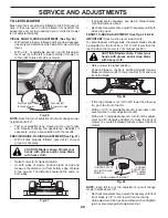
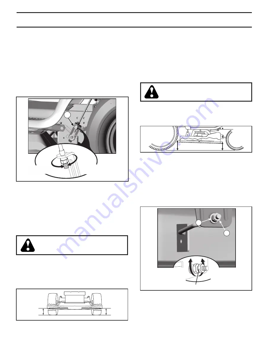
FRONT-TO-BACK ADJUSTMENT (See Figs. 28 & 29)
IMPORTANT:

 Deck must be level side-to-side.

To obtain the best cutting re sults, the mower blades should 

be adjusted so the front tip is 1/8" to 3/8" lower than the 

rear tip when the mower is in its highest position.

CAUTION: Blade is sharp. Protect your 

hands with gloves and/or wrap blade 

with heavy cloth.

•  Raise mower to highest position.
•  Position blade so the tip is pointing straight forward. 

Measure distance (B) to the ground at front and rear 

tip of the blade.

TO LEVEL MOWER

Make sure tires are properly inflated to the PSI shown on 

tires. If tires are over or under inflated, it may affect the 

appearance of your lawn and lead you to think the mower 

is not adjusted properly.

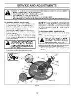
VISUAL SIDE-TO-SIDE ADJUSTMENT (See Fig. 26)

• 

With all tires properly inflated and if your lawn appears 

unevenly cut, determine which side of mower is cutting 

lower.

•  With a 3/4" or adjustable wrench, turn lift link adjust-

ment nut (A) to the left to lower LH side of mower, or, 

to the right to raise LH side of mower.

NOTE

: Each full turn of adjustment nut will change mower 

height about 3/16".
•  Test your adjustment by mowing some uncut grass 

and visually checking the appearance. Readjust, if 

necessary, until you are satisfied with the results.

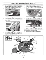
PRECISION SIDE-TO-SIDE ADJUSTMENT (See Fig. 27)

•  With all tires properly inflated, park tractor on level 

ground or driveway.

CAUTION: Blade is sharp. Protect your 

hands with gloves and/or wrap blade 

with heavy cloth.

•  Raise mower to its highest position.
•  At both sides of mower, position blade at side and 

measure the distance (A) from bottom edge of blade 

to the ground. The distance should be the same on 

both sides.

NOTE:

 Each full turn of the adjustment nut will change 

mower height about 1/8".
• 

Recheck measurements, adjust if necessary until front 

tip of blade is 1/8" to 3/8" lower than the rear tip.

• 

Hold adjustment nut in position with wrench and tighten 

jam nut securely against adjustment nut.

02966

A

A

Fig. 27

• 

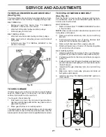
If front tip of blade is not 1/8" to 3/8" lower than the rear 

tip, go to the front of tractor.

•  With an 11/16" or adjustable wrench, loosen jam nut A 

several turns to clear adjustment nut B.

•  With a 3/4" or adjustable wrench, turn front link adjust-

ment nut (B) clockwise (ltighten) to raise the front of 

mower, or, counterclockwise (loosen) to lower the front 

mower.

Fig. 29

B

02950

A

TIGHTEN ADJUST 

NUT 

B

 TO RAISE 

MOWER

LOOSEN 

ADJUST NUT 

B

 TO LOWER 

MOWER

LOOSEN JAM NUT 

A

 FIRST

Fig. 26

02948

A

Turn nut left

to lower mower

Turn nut right

to raise mower

B

B

Fig. 28

Summary of Contents for 435057

Page 1: ...OPERATOR S MANUAL 02 11 10 SR 435057 Printed in the U S A 5000 960480001...

Page 2: ...p engine and remove keys before dismounting Disengage blades when not mowing Shut off engine and wait for all parts to come to a complete stop before cleaning the machine removing the grass catcher or...

Page 3: ...h towed equipment except at the hitch point Follow the manufacturer s recommendation for weight limits for towed equipment and towing on slopes Never allow children or others in or on towed equipment...

Page 4: ...AINTENANCE 14 17 SERVICE AND ADJUSTMENTS 18 23 STORAGE 24 TROUBLESHOOTING 25 26 WARRANTY 28 TABLE OF CONTENTS WARNING This tractor is equipped with an internal com bustion engine and should not be use...

Page 5: ...D PARTS Steering Wheel Steering Wheel 1 Washer Seat 1 Seat Steering Boot Steering Extension Shaft Steering Wheel Adapter Key s Slope Sheet 1 Hex Bolt 1 Lock Washer 1 Large Flat Washer Steering Wheel I...

Page 6: ...ition seated behind the steering wheel TOREMOVETRACTORFROMCARTON UNPACK CARTON Remove all accessible loose parts and parts cartons from carton Cut along dotted lines on all four panels of carton Remov...

Page 7: ...w the instructions below to remove the tractor from the skid WARNING Beforestarting read understandandfollow all instructions in the Operation section of this manual Be sure tractor is in a well venti...

Page 8: ...ntify safety inform ation about hazards which can result in death serious injury and or property damage DANGER indicates a hazard which if not avoided will result in death or serious injury WARNING in...

Page 9: ...the tractor and starting the engine C PARKING BRAKE Locks clutch brake pedal into the brake position D THROTTLE CHOKE CONTROL Used for starting and controlling engine speed Our tractors conform to the...

Page 10: ...emain in brake position Make sure parking brake will hold tractor secure B C STOPPING See Fig 6 MOWER BLADES To stop mower blades place attachment clutch control in the DISENGAGED position GROUND DRIV...

Page 11: ...eed of movement is controlled by the gearshift lever J 1 Start tractor with clutch brake pedal depressed and gearshift lever in neutral position 2 Move gearshift lever to desired position 3 Slowly rel...

Page 12: ...ent lift control When pushing or towing your tractor be sure gearshift lever is in neutral N position Do not push or tow tractor at more than five 5 MPH NOTE To protect hood from damage when transport...

Page 13: ...ill take extra cranking time to move fuel from the tank to the engine Sit on seat in operating position depress clutch brake pedal and set parking brake Place gear shift lever in neutral position Move...

Page 14: ...k Replace Mower Blades Che Clean Debris Off Steering Plate ck Transaxle Cooling Che Check Operator Presence ROS Systems ck V Belts Check Mower Levelness LUBRICATION CHART GENERAL RECOMMENDATIONS The w...

Page 15: ...ngine is running and the attachment clutch is engaged any attempt by the operator to leave the seat should shut off the engine The attachment clutch should never operate unless the operator is in the...

Page 16: ...y cable first then RED bat tery cable and remove battery from tractor Rinse the battery with plain water and dry Clean terminals and battery cable ends with wire brush until bright Coat terminals with...

Page 17: ...line with arrow pointing towards carburetor Be sure there are no fuel line leaks and clamps are properly positioned Immediately wipe up any spilled gasoline Fig 18 ENGINE COOLING SYSTEM See Fig 17 Deb...

Page 18: ...BE MOUNTED ON THE TRACTOR REMOVE THE FRONT LINK E AND REAR LIFT LINKS C FROM TRACTOR AND HOOK THE CLUTCH SPRING Q INTO THE CABLE GUIDE ON FRONT EDGE OF LOWER DASH TO INSTALL MOWER See Fig 20 25 Be su...

Page 19: ...nd secure with retainer spring Repeat on opposite side of tractor ATTACH REAR LIFT LINKS C Lift rear corner of mower and position slot in link assembly over pin D on rear mower bracket and secure with...

Page 20: ...ut will change mower height about 3 16 Test your adjustment by mowing some uncut grass and visually checking the appearance Readjust if necessary until you are satisfied with the results PRECISION SID...

Page 21: ...ate then the brakeneedstobeserviced Contactaqualifiedservicecenter 02954 Manual A B D E F G TO REPLACE MOTION DRIVE BELT See Fig 31 Park the tractor on level surface Engage parking brake For assistanc...

Page 22: ...nwhenaround batteries If your battery is too weak to start the engine it should be recharged See BATTERY in the MAINTENANCE sec tion of this manual If jumper cables are used for emergency starting fol...

Page 23: ...ghten securely Lower seat pan INTERLOCKS AND RELAYS Loose or damaged wiring may cause your tractor to run poorly stop running or prevent it from starting Checkwiring SeeelectricalwiringdiagramintheRep...

Page 24: ...FUELSYSTEMPARTSSUCH AS CARBURETOR FUEL FILTER FUEL HOSE OR TANK DURING STORAGE ALSO EXPERIENCE INDICATES THAT ALCOHOL BLENDED FUELS CALLED GASOHOL OR USING ETHANOLORMETHANOL CANATTRACTMOISTUREWHICH LE...

Page 25: ...wn fuse 4 Replace fuse 5 Corroded battery terminals 5 Clean battery terminals 6 Loose or damaged wiring 6 Check all wiring 7 Faulty ignition switch 7 Check replace ignition switch 8 Faulty solenoid or...

Page 26: ...Replace blade Tighten blade bolt 7 Buildup of grass leaves and trash under mower 7 Clean underside of mower housing 8 Mower drive belt worn 8 Replace mower drive belt 9 Blades improperly installed 9 R...

Page 27: ...never across the face Do not mow slopes greater than 15 degrees Make turns gradually to prevent tipping or loss of control Exercise extreme caution when changing direction on slopes 1 Fold this page a...

Page 28: ...s used for rental or commercial purposes is limited to 90 days from the date of original purchase 5 This Warranty applies only to products which have been properly assembled adjusted operated and main...

Reviews: