22
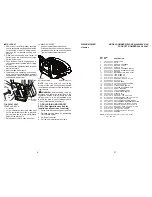
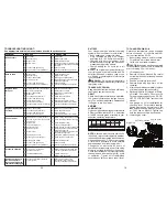
TO LEVEL MOWER HOUSING
Adjust the mower while riding mower is
parked on level ground or driveway. Ensure
tires are properly inflated. If tires are over or
underinflated, you will not properly adjust
your mower.
SIDE-TO-SIDE ADJUSTMENT
• Raise mower to its highest position.
• Measure dis
tance "A" from bot tom edge
of mower to ground level at front corners
of mower.
A
A
Bottom Edge of
Mower to Ground
Bottom Edge of
Mower to Ground
• To raise the right side of the mower, tighten
lift link adjustment nut.
• To lower the right side of the mower, loosen
lift link adjustment nut.
NOTE
: Each full turn of adjustment nut will
change mower height about 3/16".
• Recheck measurements after ad just ing.
F
F
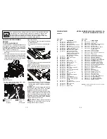
FRONT-TO-BACK ADJUSTMENT
IMPORTANT:
Deck must be level side-to
side.
To obtain the best cutting results, the mower
housing should be adjusted so that the front
is approximately 1/8" to 1/2" lower than the
rear when the mower is in its highest position.
Check adjustment on right side of riding
mower. Measure dis tance “F” directly in front
and behind the mandrel at bottom edge of
mower housing as shown.
Nut
"G"
Nut
"H"
Trunnion
• To lower front of mower housing turn nuts
“G” and “H” clockwise.
• When distance “F” is 1/8" to 1/2" lower
at front than rear, tighten nut “H” against
trunnion on front link.
• To raise front of mower housing turn nuts
“G” and “H” counter clockwise.
• When distance “F” is 1/8" to 1/2" lower
at front than rear, tighten nut “H” against
trun nion on front link.
NOTE:
Each full turn of "G" will change "F"
by approximately about 3/8".
• Recheck side-to-side adjustment.
Turn nut right
to lower mower
Turn nut left
to raise mower
Adjustment Nut
23
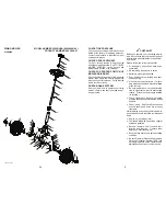
TO ADJUST STEERING WHEEL
ALIGNMENT
If steering wheel crossbars are not horizontal
(left to right) when wheels are positioned
straight forward, remove steering wheel
and reassemble per instructions in the
"INSTALL STEERING COLUMN" section
of this manual.
TO REMOVE WHEEL FOR REPAIRS
FRONT WHEEL
1. Block up front axle securely.
2. Remove dust cover, retaining ring, and
washer to allow wheel removal.
3. Repair tire and reassemble.
4. Replace washer and retaining ring
securely in axle groove.
REAR WHEEL
1. Block up rear axle securely.
2. Remove dust cover, retaining ring, wash-
er, and square key while pulling tire off.
3. Repair tire and reassemble.
4. Replace square key while putting tire back
on, then replace washer and retaining
ring securely in axle groove.
NOTE:
To seal tire punctures and pre vent
flat tires due to slow leaks, purchase and
use tire sealant from authorized service
center. Tire sealant also pre vents tire dry
rot and corrosion.
Retaining
Ring
Dust
Cover
Washer
Square Key
(rear wheel only)
TO CHECK BRAKE
If riding mower requires more than four (4)
feet to stop at highest speed in highest gear
on a level, dry concrete or paved surface,
then brake must be serviced.
You may also check brake by:
1. Park riding mower on a level, dry con-
crete or paved surface, depress clutch/
brake pedal all the way down and engage
parking brake.
2. Place motion control lever in neutral
position.
The rear wheels must lock and skid when
you try to manually push the riding mower
forward. If the rear wheels rotate, then the
brake needs to be serviced. Contact a quali-
fied service center.
TO REPLACE MOWER BLADE DRIVE
BELT
MOWER DRIVE BELT REMOVAL
1. Park riding mower on a level surface.
2. Set parking brake.
3. Lower mower to its lowest position.
4. Remove mandrel cover from mower deck.
5. Remove rear engine plate from unit.
6. Remove rear belt keeper from unit.
7. Carefully roll belt over the top of the
mower blade mandrel.
8. Remove belt from idler pulleys.
9. Check idler pulleys to see that they rotate
freely.
10. Remove belt from rear drive pulley.
MOWER DRIVE BELT INSTALLATION
Install in reverse order following instruc-
tions in "MOWER DRIVE BELT REMOVAL"
section.
Belt
Keeper
Mower Drive Belt
Idler Pulleys
Mandrel

