background image

Summary of Contents for One 28600

Page 1: ...Operator s ual 26 RiDiNG MOWER SiDE DISCHARGE ELECTRIC START Catalog No 28600 iMPORTANT Read and follow all Safety Rules and Instructions before operating this equipment Patents Pending 436518 Rev 3 ...

Page 2: ...y must be maintained in accordance with the instructions furnished 4 The Warranty does not apply to any products used for rental or commercial purposes 5 This Warranty applies only to products which have been properly assembled adjusted operated and maintained in ac cordance with the instructions furnished This Warranty does not apply to any product which has been subjected to altera tion misuse a...

Page 3: ...achine if anyone enters the area Never carry passengers Do not mow in reverse unless absolutely necessary Always look down and behind before and while backing Never direct discharged material toward anyone Avoid discharging material against a wall or obstruction Material may ricochet back toward the operator Stop the blade when crossing gravel surfaces Do not operate machine withoutthe entire gras...

Page 4: ... sud denly roll over if a wheel is over the edge or if the edge caves in Iii CHILDREN Tragic accidents can occur if the operator is not alert to the presence of children Children are often attracted to the machine and the mowing activity Never assume that children will remain where you last saw them Keep children out ofthe mowing area and in the watchful care of a responsible adult other than the ...

Page 5: ...ition Never tamper with safety devices Check their proper operation regularly Keep machine free of grass leaves or other debris build up Clean oil or fuel spill age and remove any fuel soaked debris Allow machine to cool before storing If you strike a foreign object stop and inspect the machine Repair if necessary before restarting Never make any adjustments or repairs with the engine running Chec...

Page 6: ...d forest covered brush covered or grass covered land unless the engine s exhaust system is equipped with a spark arrester meeting applicable local or state laws if any If a spark arrester is used it should be maintained in effective working order by the operator In the state of Californiathe above is required by law Section 4442 of the California Public Resources Code Other states may have similar...

Page 7: ...es on unit HOW TO SET UP YOUR RIDING MOWER INSTALL STEERING COLUMN 3 Insert steering shaft into mount and se curely fasten with bolt washer and nut provided Insert pin into hole in steering shaft Slide plastic cover over steering shaft and into position _ Steering Shaft Plastic Cover Pin _ Steering Shaft Mount Bolt 4 Slide steering shaft protective foam cover over shaft 5 Position front wheels of ...

Page 8: ...s clear of other people and objects TO ROLL RIDING MOWER OFF SKID See Operation section for location and function of controls 1 Raise deck lift lever to its highest position 2 Release parking brake by depressing clutch brake pedal 3 Engage freewheel control See TO TRANSPORT in the operation section of this manual 4 Roll riding mower forward off skid CHECK TIRE PRESSURE The tires on your riding mow...

Page 9: ...elt Be sure it is routed properly around pulleys and inside all belt keepers _ Check wiring See that all connections are still secure and wires are properly clamped _ Before driving riding mower be sure free wheel control is in transmission engaged position see TO TRANSPORT in the Operation section of this manual While learning how to use your riding mower pay extra attention to the following impo...

Page 10: ...ailure to follow instructions could result in serious injury or death The safety alert symbol is used to identify safety inform ation about hazards which can result in death serious injury and or property damage DANGER indicates a hazard which if not avoided will result in death or serious injury WARNING indicates a hazard which if not avoided could result in death or serious injury CAUTION indica...

Page 11: ...n National Standards Institute DECK CLUTCH LEVER Used to engage the mower blade BRAKE PEDAL Used for braking the rid ing mower and starting the engine HEIGHT ADJUSTMENT LEVER Used to adjust mower cutting height IGNITION SWITCH Used for starting and stopping the engine LIFT LEVER PLUNGER Used to release height adjustment lever when changing its position PARKING BRAKE LEVER Locks park ing brake into...

Page 12: ... dead NOTE Under certain conditions when riding mower is standing idle with the engine run ning hot engine exhaust gases may cause browning of grass To eliminate this pos sibility always stop engine when stopping riding mower on grass areas M _HiICAUTION Always stop riding mower completely as described above before leaving the operator s position TO MOVE FORWARD AND BACKWARD The direction and spee...

Page 13: ...e Operation System ROS Any attempt by the operator to travel in the reverse direc tion with the deck clutch engaged will shut off the engine unless ignition key is placed in the ROS ON position _WARNING Backing up with the deck clutch engaged while mowing is strongly discouraged Turning the ROS ON to al low reverse operation with the deck clutch engaged should only be done when the operator decide...

Page 14: ...nance section in this manual ADD GASOLINE Fill fuel tank to bottom of filler neck Do not overfill Use fresh clean regular unleaded gasoline with a minimum of 87 octane Use of leaded gasoline will increase carbon and lead oxide deposits and reduce valve life Do not mix oil with gasoline Purchase fuel in quantities that can be used within 30 days to assure fuel freshness _ICAUTION Wipe off any spill...

Page 15: ...the attachment being used Starter Handle MOWING TiPS Mower should be properly leveled for best mowing performance See TO LEVEL MOWER HOUSING in the Service and Adjustments section of this manual The left hand side of mower should be used for trimming Drive sothat clippings are discharged onto the area that has already been cut Have the cut areato the right of the riding mower This will result in a...

Page 16: ...g mower does not cover items that have been subjected to operator abuse or negligence To receive full value from the warranty operator must maintain riding mower as instructed in this manual Some adjustments will need to be made periodically to properly maintain your riding mower At least once a season check to see if you should make any of the adjustments described in the Service and Adjustments ...

Page 17: ... When the engine is running and the deck clutch lever is engaged any at tempt by the operator to leave the seat should shut off the engine The deck clutch lever should never operate unless the operator is in the seat CHECK REVERSE OPERATION ROS SYSTEM When the engine is running with the ignition switch in the engine ON posi tion and the deck clutch lever engaged any attempt by the operator to shif...

Page 18: ...ion and wear after 100 hours of operation and replace if neces sary The belt is not adjustable Replace belt if it begins to slip from wear ENGINE LUBRICATION Only use high quality detergent oil rated with API service classification SG SL Select the oil s SAE viscosity grade according to your expected operating temperature SAE VISCOSITY GRADES I F 20 0 30 32 40 60 80 100 o _0 2 1 1 _0 _o 4 TEMPERAT...

Page 19: ...move dirt and stubborn dried gum fibers CLEAN AIR INTAKE COOLiNG AREAS To ensure proper cooling make sure the grass screen cooling fins and other exter nal surfaces of the engine are kept clean at all times Every 100 hours of operation more often under extremely dusty dirty conditions remove the blower housing and other cooling shrouds Clean the cooling fins and external surfaces as necessary Make...

Page 20: ...ER 1 Place deck clutch in DISENGAGED position 2 Move mower height adjustment lift lever forward to lower mower to its lowest position 3 Remove mandrel cover 4 Remove pins holding left and right front mower suspension arms in place 5 Remove bolt holding deck front to rear leveling rod in place 6 Remove pin holding deck lift link arm in place 7 Remove bolt holding deck side to side leveling rod in p...

Page 21: ...nt on right side of riding mower Measure distance F directly in front and behind the mandrel at bottom edge of mower housing as shown To lower front of mower housing turn nuts G and H clockwise When distance F is 1 8 to 1 2 lower at front than rear tighten nut H against trunnion on front link To raise front of mower housing turn nuts G and H counter clockwise When distance F is 1 8 to 1 2 lower at...

Page 22: ...ement TO ADJUST STEERING WHEEL ALIGNMENT If steering wheel crossbars are not horizontal left to right when wheels are positioned straight forward move steering wheel and reassemble per instructions in the INSTALL STEERING COLUMN section of this manual TO REMOVE WHEEL FOR REPAIRS FRONT WHEEL 1 Block up front axle securely 2 Remove dust cover retaining ring and washer to allow wheel removal 3 Repair...

Page 23: ...nt Your carburetor is not adjustable If your engine does not operate properly due to suspected carburetor problems take your riding mower to a qualified service center for repair and or adjustment IMPORTANT Never tamper with the engine governor which is factory set for proper en gine speed Overspeeding the engine above the factory high speed setting can be danger ous If you think the engine govern...

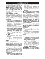
Page 24: ...ation and formation of acids during storage Acidic gas can damage the fuel system of an engine while in storage Empty the fuel tank by starting the engine and letting it run until the fuel lines and carburetor are empty Never use engine or carburetor cleaner products in the fuel tank or permanent damage may occur Use fresh fue next season NOTE Fuel stabilizer is an acceptable al ternative in minim...

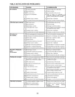
Page 25: ...an battery terminals 6 Check all wiring 7 Check replace ignition switch 8 Check replace solenoid or starter 9 Faultyoperatorpresenceswitch es 1 Weak or dead battery 2 Corroded battery terminals 3 Loose or damaged wiring 4 Faulty solenoid or starter 1 Cutting too much grass too fast 2 Build up of grass leaves and trash 9 Contact a qualified service center 1 Recharge or replace battery 2 Clean batte...

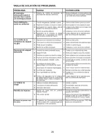
Page 26: ...ve 1 Freewheel control in DISENGAGED position 2 Axle key missing Engine dies when 1 Reverse operation system ROS tractor is shifted is not ON while mower or other into reverse attachment is engaged CORRECTION 1 Check wiring switches and connections If not corrected contact a qualified service center 1 Replace blade Tighten blade bolt 2 Level mower deck 3 Clean underside of mower housing 4 Contact ...

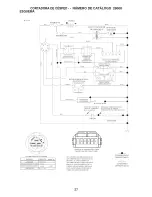
Page 27: ... t t j i L I I 11 q 1 IGNITION UNIT SPARK PLUG GAP q q CHARGING SYSTEM OUTPUT 28 VOLTS AC MIN _ 3600 RPM 5 AMP DC _l 3600 RPM CHARGING SYSTEM DISCONNECTED DIODE STATOR IGNITION SWITCH POSITION CIRCUIT MAKE OFF M G A 1 RUN OVERRIDE B A1 RUN B A1 L A2 START B S A1 SAFETY START MODULE 7 VIE _ ED FROM MATING SIDE WIRING INSULATED CLIPS NOTE IF WIRING INSULATED CLIPS WERE REMOVED FOR SERVICING OF UNIT ...

Page 28: ...ELECTRICAL RIDING MOWER CATALOG NO 28600 LRV1 11 10 9 8 J t m j i g J _ i r i i i i i 12 5 3 4 2 7 28 ...

Page 29: ...8 11 431846 12 192749 13 428477 DESCRIPTION BATTERY FOAM POLYURETHANE SWITCH IGN DLTA P IN ROS KEY MOLDED FUSE 5A FUSE 40A SWITCH PLUNGER NO OLIVE RELAY 40A SWITCH INTLK CL MWR GRY SWITCH INTERLOCK NONC GRAY MODULE STARTING RECOIL LRV SWITCH SEAT DP ROS HARNESS IGN ELECTSTART LRV NOTE All component dimensions given in U S inches 1 inch 25 4 mm 29 ...

Page 30: ...CHASSIS RIDING MOWER CATALOG NO 28600 14 42 lO 45 LRV Chassis f r2 30 ...

Page 31: ...FRONT BRACE AXLE CROSS COVER FRICTION DRIVE PLATE ENGINE BRACKET CHASSIS FRONT BRACKET STEERING SUPPORT PAN SEAT BRACKET SWITCH MOUNTING BOOT DUST COVER FOOT REST STRUCTURE FOOT REST SUPPORT FOOT REST FENDER CONTROL GUARD ENGINE ENGINE NON CALIFORNIA 12S907 1411 B1 ENGINE CALIFORNIA 121S07 1415 F1 ENGINE CANADA 12S907 1463 B1 KEEPER BELT BRACKET BATTERY LEVER SWITCH DECK CLUTCH ASM KNOB SCREW NO 1...

Page 32: ...DRIVE RIDING MOWER CATALOG NO 28600 70 38 LRV Drive 1 r3 32 ...

Page 33: ...58 4497H BRACE CARRIER REAR 59 17490508 SPRING CARRIER 60 428460 SPRING BRAKE 61 427945 SPRING BYPASS 62 429678 BRACE CARRIER BOX 63 77100812 LINK SHIFT 64 76020208 ARM CLUTCH 65 429325 WELDMENT SHIFT LEVER 66 429694 SUPPORT SHIFT LEVER 67 429693 WASHER NYLON 68 17490406 HUB SHIFT LEVER 69 428070 SPACER NYLON 70 17000512 MNTG BRKT SHIFT ARM 71 BRACKET SHIFTER FLEX 72 TUBE SHIFT ARM 73 GRIP HANDLE ...

Page 34: ...STEERING RIDING MOWER CATALOG NO 28600 526 23 22 7_ __28 LRV Steering_l_r2 34 2_c ...

Page 35: ...HEEL ASM FRONT E CLIP WASHER HARDENED WASHER 1 4 X 3 4 SPINDLE RH WASHER HARDENED THRUST BUSHING STEERING COLUMN PIN 5 64 X 3 4 COTTER WASHER WELDMENT LWR STRG SHAFT LINK STRNG LH LINK STRNG RH BOLT 5 16 18 X 1 1 2 WASHER NUT 5 16 18 BUSHING STEERING SNAP SUPPORT UPPER STEERING BUSHING UPPER STEERING BOLT 5 16 18 X 3 4 CLIP RETAINER SPRING COVER STEERING COLUMN SHAFT STEERING ADAPTER STEERING WHEE...

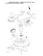
Page 36: ...RIDING MOWER CATALOG NO 28600 MOWER DECK 9 24 14 LRV Deck I r4 17 36 ...

Page 37: ... 194208 PIN 21 19171912 WASHER 17 32 X 1 3 16 22 429350 LINK DECK 23 73930600 NUT LCK 3 8 16 24 429531 SPRING DECK 25 4497H PIN 26 187690 SPACER MANDREL 27 173984 BOLT MANDREL 28 400234 NUT LOCK 29 428500 BLADE 30 193003 BOLT BLADE 31 193197 PULLEY IDLER 32 141043 GUARD IDLER 33 193414 KEEPER BELT IDLER 34 72110612 BOLT 3 8 16 X 1 1 2 35 199470 ARM BRAKE 36 137729 SCREW 1 4 20 X 5 8 37 73900600 NU...

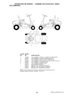
Page 38: ... 436520 436519 DESCRIPTION DECAL STEERING WHEEL DECAL V BELT SCH 30 DECAL WARN DEFLECT CTFGR DECAL DECK DEFLECTOR DECAL SPARK ARRESTOR DECAL WARNING DECAL BYPASS MANUAL OPERATOR ENGLISH MANUAL OPERATOR FRENCH MANUAL OPERATOR SPANISH NOTE All component dimensions given in U S inches 1 inch 25 4 mm 38 California models only ...

Page 39: ...pes greater than 15 degrees Make turns gradually to prevent tipping or loss of control Exercise extreme caution when changing direction on slopes 1 Fold this page along dotted line indicated above 2 Hold page before you so that its left edge is vertically parallel to a tree trunk or other upright structure 3 Sight across the fold in the direction of hill slope you want to measure 4 Compare the ang...

Page 40: ...urer s I D Number b Description of part For Technical Assistance call 1 800 829 5886 For a Parts Manual go to our website www weedeater com NOTE HOP provides parts and service through its authorized distributors and dealers therefore all requests for parts and service should be directed to your local dealer s The philosophy of HOP is to continually improve all of its products If the operating char...

Page 41: ...radorf CORTA RA DE CESPED DE 26 DESCARGA LATERAL f ARRAN LIE ELECTRICO N_mero 28600 Catalogo IMPORTANTE Lea y siga todas la Reglas e Instrucciones de Seguridad antes de operar este equipo Patents Pending 436519 Rev 3 ...

Page 42: ...a venta original Se debe dar mantenimiento a la bateria de acuerdo con las instrucciones provistas 4 La garantia no aplica a ningOn producto que se use con prop6sitos de renta o comerciales 5 Esta garantia aplica Onicamente a productos que se han armado ajustado operado y mantenido de acuerdo con las instrucciones provistas Esta garantia no aplica a ningOn producto que se haya sometido a alteracio...

Page 43: ...lutamente necesario Siempre mire hacia abajo y hacia atr s antes y cuando vaya en reversa Nunca dirija el material que se descarga hacia nadie Evite descargar el material contra una pared u otra obstrucci6n El material puede rebotar hacia el operador Detenga la cuchilla cuando cruce pot superficies con grava No maneje la m quina si no tiene el co lector de cesped completo la canaleta de descarga u...

Page 44: ...e en el suelo No corte cerca de declives zanjas oterra plenes La m_ quina podria volcarse de repente si una rueda pasa sobre la orilla o si la orilla termina en un hoyo Iii NINOS Pueden ocurrir accidentes tr_ gicos si el operador no esta alerta ante la presencia de nihos Con frecuencia los nihos se sienten atraidos por la maquina y la activi dad de corte de cesped Nunca de por un hecho que los nit...

Page 45: ...el equipo se encuentra en condiciones de trabajo seguras Nunca manipule los dispositivos de segu ridad Revise con regularidad que operen bien Mantenga la m quina libre de cualquier acumulaci6n de cesped hojas u otra basura Limpie los derrames de aceite o combustible y retire cualquier basura que contenga combustible Permita que la m quina se enfrie antes de almacenar la Si usted golpea un objeto e...

Page 46: ...bosques sin mejoras cubiertos de arbustos o cu biertos de pastos a menos que el sistema de escape del motor este equipado con un parachispas que cumpla con las leyes loca les o estatales aplicables de haberlas Si se usa un parachispas el operador deber darle mantenimiento en un orden de trabajo efectivo En e estado de California las leyes exigen el uso de un parachispas Secci6n 4442 del C6digo de ...

Page 47: ... unidad COMO CONFIGURAR SU CORTADORA DE ClaSPED INSTALACION DE COLUMNA DE DIRECCION 1 Inserte el eje de direcci6n en el montaje y apriete bJen con el perno la arandela y la tuerca provistas 2 Inserte el pasador en el orificio del eje de direcci6n 3 Deslice la cubierta de pl_ stico sobre el eje de direcci6n y en su posici6n Eje de direcci6n _ Cubierta plfistico de Pasador Montaje del eje de direcci...

Page 48: ...raci6n para vet la ubicaci6n y funci6n de los controles 1 Eleve la palanca de elevador de la plataforma hasta su posici6n m xima 2 Suelte el freno de estacionamiento al liberar el pedal del embrague freno 3 Active el control de la rueda libre Con suite la parte de TRANSPORTE en la secci6n de Operaci6n de este manual 4 Saque la cortadora de cesped de la tarima REVISE LA PRESION DE LAS LLANTAS Las I...

Page 49: ...ededor de las poleas y adentro de todas las sujeciones de la cinta Vf Revise e cableado AsegOrese de que to das las conexiones esten bien colocadas y que los cables esten bien sujetos _ Antes de conducir la cortadora de cesped asegOrese de que el control de la rueda libre este en la posici6n de transmisi6n activada consulte la parte de TRANS PORTE en la secci6n de Operaci6n de este manual AI apren...

Page 50: ... reglas de seguridad PELIGRO indica un peligro que si no se evita provoca muerte o lesiones graves PEDAL DE FRENO EMBRAGUE ADVERTENClA indica un peligro que si no se evita puede provocar muerte o lesiones graves PRECAUCION indica un peligro que si no se evita puede provocar lesiones ligeras o moderadas CONTROL DE RUEDALIBRE ACTIVADO PRECAUClON cuando se utiliza sin el s_mbolo de aviso indica una s...

Page 51: ... PLATAFORMA Se usa para activar la cuchilla de la cortadora de cesped PEDAL DEL FRENO Se usa para frenar la cortadora de cesped y arrancar el motor PALANCA DE AJUSTE DE ALTURA Se usa para ajustar la altura de corte de la cortadora de cesped INTERRUPTOR DE ARRANQUE Se usa para arrancar y detener e motor I_MBOLO DE LA PALANCA DEL ELE VADOR Se usa para soltar la palanca de ajuste de altura cuando se ...

Page 52: ... evitar su uso no autorizado IMPORTANTE Dejar el interruptor de arranque en una posici6n que no sea la de PARAD _ causar que la baterfa se descargue y quede muerta NOTA Bajo ciertas condiciones cuando la cortadora de cesped est parada con el motor funcionando los gases de escape del motor caliente pueden causar que el cesped se tome marr6n Para evitar esta posibilidad detenga siempre el motor cuan...

Page 53: ...as con este o sin la coraza del deflector en su sitio FUNClONAMIENTO ATRAS Tu tractor est equipado con el Sistema de Funcionamiento Atr s ROS Cual quier tentativa del operador de viajar marcha atr s con el embrague puesto apagar el motor a menos que la Ilave de ignici6n se ponga en la posici6n de ON del ROS ATENClON Ir marcha atr s con e em brague puesto para cortar no es reco mendable Poniendo e ...

Page 54: ...n un patio reinserte la varilla y atornille bien el tap6n espere unos cuantos segundos retire o y verifi que el nivel del aceite Si es necesario agregue aceite hasta que llegue a la marca que dice LLENO en la varilla No Io Ilene de m s Para operarla en clima frio usted debe cambiar el aceite para obtener un arranque m s f cil Consulte la tabla de viscosidad de aceite de la secci6n de Mantenimiento...

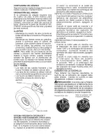
Page 55: ...a plataforma en la posici6n desactivada 5 Jale la cuerda manual para arrancar el motor C ONSEJOS PARA CORTAR EL CESPED La cortadora de cesped debe estar bien nivelada para que su desempeho sea e mejor Consulte la parte de NIVELACION DE LA CARCASA DE LA CORTADORA DE CESPED en la secci6n de Servicio y Ajustes de este manual El lado izquierdo de la cortadora de cesped se debe usar para podar Conduzca...

Page 56: ... para esta cortadora de cesped no ampara los articulos que se han sometido al abuso o la negligencia del operador Para recibir el valor completo de la garantia el operador debe darle mantenimiento a la cortadora de cesped conforme se indica en este manual Ser necesario hacer algunos ajustes en forma peri6dica para mantener de manera correcta la cortadora de cesped AI menos una vez cada temporada r...

Page 57: ...RESENCIA OPERADOR Cuando el motor esta en marcha cualquier tentativa del operador de abandonar el asiento sin haber puesto el freno de estacionamiento primero apagar el motor Cuando el motor est en marcha y e embrague del accesono est conectado cualquier tentativa del operador de abandonar el asiento apagar e motor El embrague del accesorio no tendria que funcionar nunca si el operador no est en s...

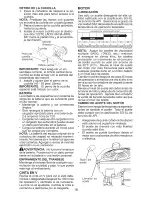
Page 58: ...ciedad y paja Io que puede restringir el enfriamiento ClNTA EN V Revise la cinta en V para ver si est dete riorada o desgastada despues de 100 horas de operaci6n y c_ mbiela si es necesario La cinta no es ajustable Cambie la cinta si comienza a deslizarse por el desgaste MOTOR LUBRICACKSN Use s61o un aceite detergente de alta ca lidad calificado con la clasificaci6n SG SL de servicio de API Selecc...

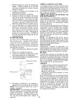
Page 59: ...lentamiento Limpie con un cepillo de alambre o con aire comprimido para retirar la suciedad y las fibras de goma secas dificiles e quitar LIMPIE LAS AREAS DE ENTRADA DE AIRE ENFRIAMIENTO Para asegurar un enfriamiento adecuado cerci6rese de que la pantalla de cesped las aletas de enfriamiento y otras superficies externas del motor se mantengan limpias en todo momento Cada 100 horas de operaci6n con...

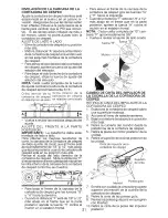
Page 60: ...rtadora de cesped a su posici6n m s baja 3 Retire la cubierta del mandril 4 Retire los pasadores que sostienen en su lugar los brazos de suspensi6n frontales izquierdo y derecho de la cortadora de cesped 5 Retire el perno que sostiene en su lugar la varilla de nivelaci6n del frente a la parte posterior de la plataforma 6 Retire el pasador que sostiene en su lugar el brazo del eslab6n del elevador ...

Page 61: ...lta Revise el ajuste del lado derecho de la cortadora de cesped Mida la distancia F directamente en frente y detr_ s del mandril en la orilla inferior de la carcasa de la cortadora de cesped conforme se muestra Para bajar el frente de la carcasa de la cortadora de cesped gire las tuercas G y H hacia la derecha Cuando la distancia F este de 1 8 a 1 2 m s abajo en el frente que en la parte posterior...

Page 62: ...ellador para Ilantas E sellador de Ilantas tambien previene la podredura en seco y la corrosi6n de las Ilantas Arandela Anillo retenedor _t Pastilla de frenos Tuerca 4 Apriete la tuerca de pinza hasta que alcance el espacio de 02 NOTA Puede ser necesario usar un ca librador de hoja para obtener la medida correcta AJUSTE DE LA ALINEACI6N DEL VOLANTE Si los travesaSos del volante no est n en posici6...

Page 63: ...lesi6n personal Si usted cree que el motor est funcionando demasiado r pido o demasiado lento Ileve su cortadora de cesped a un centro de servicio calificado para su reparaci6n y o ajuste El carburador no es ajustable Si el motor no opera bien y sospecha que es debido a problemas del carburador Ileve su cortadora de cesped a un centro de servicio calificado para su reparaci6n y o ajuste IMPORTANTE...

Page 64: ...os durante el almacenamiento El gas cido puede dar_ar el sistema de combus tible de un motor mientras se encuentra en almacenamiento Vacie el tanque de combustible al arrancar el motor y dejarlo funcionar hasta que las lineas de combustible y el carburador esten vacios Nunca use productos limpiadores para motor o carburador en el tanque de com bustible porque puede ocurrir un daho permanente Use c...

Page 65: ...oso 4 Desactive el embrague de la plataforma Recargue o cambie la bateria Oambie el fusible Limpie las terminales de la bateria Revise todo el cableado Revise cambieel interruptorde arranque Revise cambie el solenoide o arranque Contactea uncentrode servioiooalificado Recargue o cambie la bateria Limpie las terminales de la bateria Revise todo el cableado Revise cambie el solenoide o arranque Perd...

Page 66: ...6sped hQmedo 2 Permita queelcesped seseque antes depodarlo 3 Plataforma decortadora decesped nonivelada 3 Nivelelaplataforma dela cortadora decesped 4 Presi6n deairedelasIlantasbaja nouniforme 4 Revise quela PSIdelasIlantasseaadecuada 5 Cuchilla desgastada dobladao suelta 5 Cambie afile la cuchilla Apriete el perno de la cuchilla 6 Acumulaci6nde cesped hojasv 6 Limpiela parte inferiordela carcasad...

Page 67: ...AD DE ENCENDIDO HLTCO DE BUJIA SALIDA DEL SISTEiVL DE MiNIMO DE CORRIENTE ALTERNA ARGA DE 5 AiVlPERIOS DE 28 VOLTIOS 3600 RPM DE CC 3600 _M COBRO DE SISTE_L_ DESCON_ECT _O t q DIODO ESTATOR INTERRL TOR DE ENCENDIDO POSICION CIRCUITO _ a RCA APAG _O M G A 1 _NTR FN FL_ C ION_TO _ _AR B AI _ONER ENFUNCIONAMIENTO B A 1 L A2 ARtLa NCAR 3 S AI MODLZO DE SEGURIDAD ES VISTO DESDE LADO DE CON_ TANDO NOTA ...

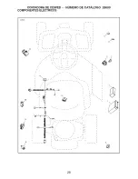
Page 68: ...CORTADOR _ DE ClaSPED NOMERO DE CATALOGO 28600 COMPONENTES ELECTRICOS LRV1 11 10 9 8 l I i i i i i i i i i i i i i s i i i i i i u t s s i a i s i i i i i 1 i i t 12 5 6 3 4 2 7 28 ...

Page 69: ... IGNICI6N ROS 4 411934 LLAVE 5 433330 FUSIBLE 5A 6 425937 FUSIBLE 40A 7 160784 INTERRUPTOR 8 431542 RELE _ 40A 9 109553X INTERRUPTOR 10 176138 INTERRUPTOR 11 431846 RETROCESO QUE COMIENZA MODULO LRV 12 192749 INTERRUPTOR ROS 13 428477 GUARNICIONES DE IGNICION NOTA Las dimensiones de todos los componentes se proporcionan en pulgadas estadounidenses 1 pulgada 25 4 mm 29 ...

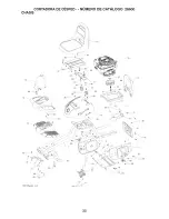
Page 70: ...CORTADORA DE Ce SPED NOMERO DE L _ _ _ CHAStS 42 _ 29 30 46 4sJso_ LRV ChasSis_l r2 3O ...

Page 71: ...BLA ASIENTO ABRAZADERA MONTAJE DE INTERRUPTOR FUNDA POLVO 428251X665 CUBIERTA DESCANSO PARA PIE 428250 ESTRUCTURA DESCANSO PARA PIE 428249 SOPORTE DESCANSO PARA PIE 428241X665 CONTROL DE DEFENSA PROTECCION MOTOR MOTOR NON CALIFORNIA 12S907 1411 B1 MOTOR CALIFORNIA 121 S07 1415 F1 MOTOR CANADA 12S907 1463 B1 SUJECION CINTA ABRAZADERA BATE R A PALANCA INTERRUPTOR MVA DE PLATAFORMA DE EMBRAGUE PERILL...

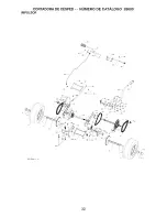
Page 72: ...CORTADORA DE ClaSPED NOMERO DE CATALOGO 28600 IMPULSOR 67 68 LRV Drive 1 r3 32 ...

Page 73: ... DE CUBO 69 429055 ESPACIADOR NAILON 428464 ABRAZADERA MNTG BRAZO 70 DEDESPLAZAMIENTO 71 428461 ABRAZADERA FLEXIONADOR 72 DE PALANCA DE CAMBIOS 73 428462 BRAZO DE DESPLAZAMIENTO DEL TUBO 196492X428 AGARRE MANIJA 72110406 73800400 165492 74780412 10040400 19091210 166002 73680400 17490436 19091016 17490420 430249 430245 428021 430247 428078 77010810 428019 428017 435253 428016 4497H 17490508 428460...

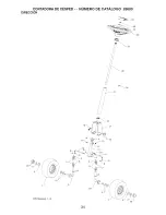
Page 74: ...CORTADORA DE CESPED NOMERO DE CATALOGO 28600 DIRECCION 526 23 22 7_ __ 28 LRV Steering_l_r2 2_c 34 ...

Page 75: ...H 428036 ESLABON STRNG RH 74780524 PERNO 5 16 18 X 1 1 2 19131016 ARANDELA 73800500 TUERCA 5 16 18 428044 MANGUITO BROCHE DE DIRECCION 428252 SOPORTE DIRECCION SUPERIOR 195227 MANGUITO DIRECCION SUPERIOR 17000512 PERNO 5 16 18 X 3 4 428045 SUJETADOR RESORTE DE RETENEDOR 428347 CUBIERTA COLUMNA DE DIRECCION 428213 EJE DIRECCION 186737 ADAPTADOR VOLANTE 19183812 ARANDELA 9 16 X 2 3 8 12 GA 73940800 ...

Page 76: ...CORTADORA DE CESPED NOMERO DE CATALOGO 28600 PLATAFORIVlA DE CORTADORA DE CESPED 23 F1 14 LRV Deck I r4 36 ...

Page 77: ... 20 194208 PASADOR 21 19171912 ARANDELA 17 32 X 1 3 16 22 429350 ESLABON PLATAFORMA 23 73930600 TUERCA CIERRE 3 8 16 24 429531 RESORTE PLATAFORMA 25 4497H PASADOR 26 187690 ESPACIADOR MANDRIL 27 173984 PERNO MANDRIL 28 400234 TUERCA CIERRE 29 428500 CUCHILLA 30 193003 PERNO CUCHILLA 31 193197 POLEA GU A 32 141043 PROTEC CION GU A 33 193414 SUJECION GUIA DE CINTA 34 72110612 PERNO 3 8 16 X 1 1 2 35...

Page 78: ...TE DE DIRECCION CALCOMANIA CORREA TRAPEZOIDAL 30 CALCOMANIA WARN DEFLECTOR CTFGR CALCOMANIA CORTADORA DE CESPED DEFLECTOR CALCOMANIA APAGACHISPAS CALCOMANIA ADVERTENCIA CALCOMANIA BYPASS MANUAL DEL OPERADOR INGLES MANUAL DEL OPERADOR FRANCES MANUAL DEL OPERADOR ESPANO NOTA Las dimensiones detodoslos componentes se proporcionan en putgadas estadounidenses 1 putgada 25 4 mm 38 Modelo California solo...

Page 79: ...endientes mayores de 15 grados Haga los virajes gradualmente para evitar volcarse o ia perdida de control Tenga mucho cuidado cuando cambie de direccibn en las pendientes 1 Plegar esta pagina a Io largo de la linea punteada arriba indicada 2 Tenet la pagina ante de si mismos de modo que su horde izquierdo sea vertical paralelo al tronco dei arboi u otra estructura vertical 3 Mirar a traves del pli...

Page 80: ...o de I D del fabricante b Descripci6n de la pieza Para obtener asistencia tecnica Ilame al 1 800 829 5886 Para obtener un manual de piezas visite nuestro sitio web www weedeater com NOTA HOP ofrece piezas y servicio a tray s de sus distribuidores y concesionarios autorizados pot Io tanto todas las solicitudes de piezas y servicio deben dirigirse a su concesionario local Es la filosofia de HOP mejo...

Reviews: