36
Nos tondeuses autoportées sont conformes aux normes en matière de sécurité
en vigueur de l’institut national des nor mes américaines.
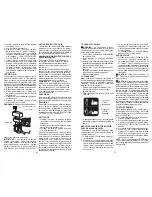
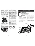
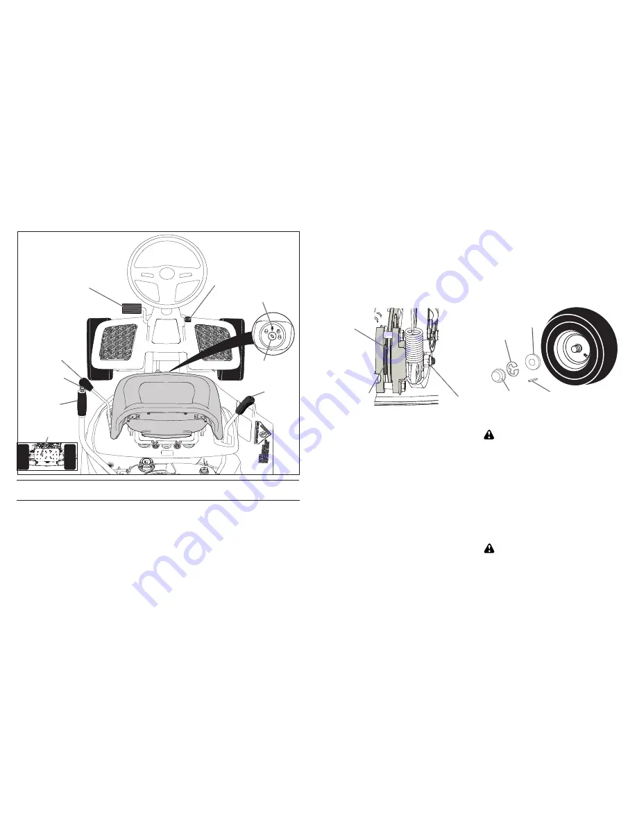
LE LEVIER DE L’EMBRAYAGE DU
PLATEAU DE COUPE -
sert à engager la
lame de la tondeuse.
La PÉDALE DE FREIN
- sert à frei ner
la tondeuse autoportée et à démarrer le
moteur.
Le LEVIER DE RÉGLAGE DE HAUTEUR
- sert à régler la hauteur de la coupe de la
tondeuse.
Le CONTACTEUR D’ALLUMAGE
- sert à
démarrer et à arrêter le moteur.
Le PISTON DU LEVIER DE LEVAGE
- sert à re lâcher le levier de réglage de
hauteur lors du chan gement de position.
Le LEVIER DU FREIN DE STATIONNE-
MENT
- verrouille le frein de stationne-
ment en position de freinage.
Le LEVIER DE COMMANDE DE MOU-
VEMENT
- sélectionne la vitesse et la
direction de la tondeuse autoportée.
La COMMANDE ROUE LIBRE
- Désen-
gage la transmission pour pouvoir pousser
ou remorquer la tondeuse autoportée avec
le moteur éteint.
ROS SUR "ON"
- Permet le fonctionne-
ment de la plate-forme de faucheuse ou
de tout autre attachement actionné tandis
qu’à l’envers.
ROS
"SUR"
Levier de
contrôle de
mouvement
Piston du levier
de levage
Commande
roue libre
Levier de
réglage de
hauteur
Levier de l’embrayage
du plateau de coupe
Pédale de frein
Pédale du frein
de stationnement
Le contacteur
d’allumage
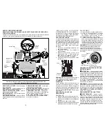
CONNAISSEZ VOTRE TRACTEUR
AVANT D’UTILISER VOTRE TRACTEUR, LISEZ CE MANUEL ET LES RÈGLES DE
SÉCURITÉ
Comparez les illustrations avec votre tondeuse autoportée afin de connaître l'emplacement
de différents réglages et co mma ndes. Conservez ce manuel aux fins de référence.
21
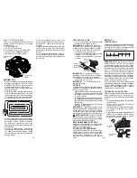
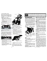
TO ADJUST BRAKE
Your riding mower is equipped with an
adjustable brake system which is mounted
on the right side of the transaxle. If riding
mower requires more than (4) feet stop-
ping distance in highest gear on a lever dry
concrete or paved surface, then brake must
be adjusted.
1. Park riding mower on a level surface.
2. Release brake/parking pedal.
3. Measure distance between rotor and
brake pad if distance between rotor and
brake pad is more than .02" gap brake
needs to be adjusted.
4. Tighten caliper nut until .02" gap is
reached.
TO ADJUST STEERING WHEEL
ALIGNMENT
If steering wheel crossbars are not horizontal
(left to right) when wheels are positioned
straight forward, move steering wheel
and reassemble per instructions in the
"INSTALL STEERING COLUMN"section of
this manual.
TO REMOVE WHEEL FOR REPAIRS
FRONT WHEEL
1. Block up front axle securely.
2. Remove dust cover, retaining ring, and
washer to allow wheel removal.
3. Repair tire and reassemble.
4. Replace washer and retaining ring
securely in axle groove.
NOTE:
To seal tire punctures and pre vent
flat tires due to slow leaks, purchase and
use tire sealant. Tire sealant also pre vents
tire dry rot and corrosion.
Retaining
Ring
Dust
Cover
Washer
Square Key
(rear wheel only)
Rotor
Nut
Brake
Pad
NOTE:
Feeler gauge may be necessary to
get correct measurement.
REAR WHEEL
1. Block up Rear axle securely.
2. Remove dust cover, retaining ring, wash-
er, and square key while pulling tire off.
3. Repair tire and reassemble.
4. Replace square key while putting tire back
on, then replace washer and retaining ring
securely in axle groove ,when pushing
tire back onto shaft reach under and pull
chain sprocket toward you to ease tire
replacement.
TO START ENGINE WITH A WEAK
BAT TERY
CAUTION:
Lead-acid batteries gen er ate
ex plo sive gases. Keep sparks, flame and
smoking ma te ri als away from bat ter ies. Always
wear eye pro tec tion when around batteries.
If your battery is too weak to start the engine,
it should be recharged. (See "BATTERY" in
the Maintenance section of this man u al).
NOTE:
This unit is equipped with an engine
recoil starting system that can be used if the
battery is too weak to start. See “RECOIL
STARTING SYSTEM” in operation section
of this manual.
REPLACING BATTERY
WARNING:
Do not short bat tery ter mi-
nals by al low ing a wrench or any other object
to contact both terminals at the same time.
Before con nect ing battery, remove metal
bracelets, wrist watch bands, rings, etc.
Positive terminal must be connected
first to prevent spark ing from ac ci den tal
grounding.

