background image

23

SERVICE AND ADJUSTMENTS

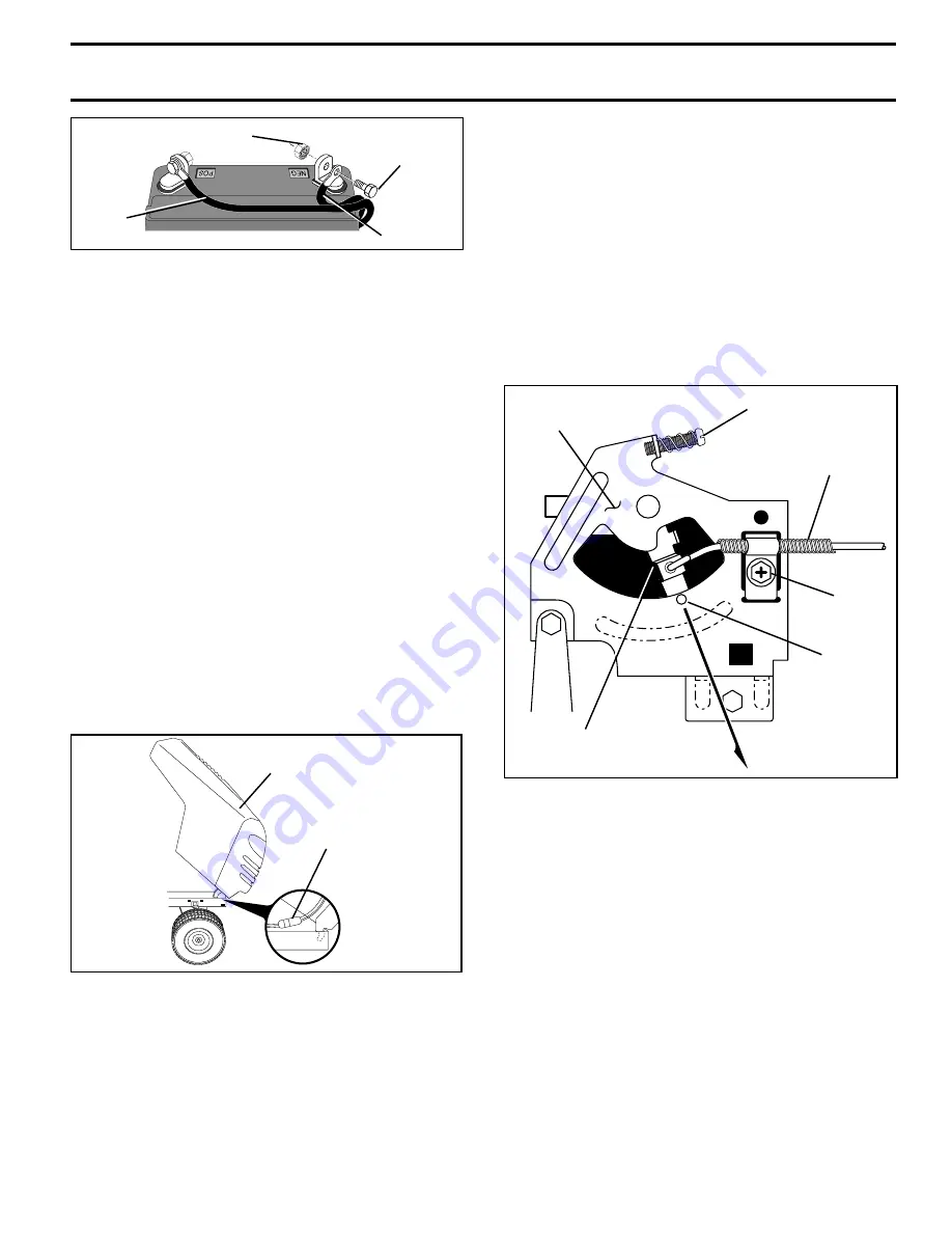
FIG. 28

KEPS NUT

HEX
BOLT

POSITIVE
(RED)
CABLE

NEGATIVE
(BLACK)
CABLE

TO REMOVE HOOD AND GRILL ASSEMBLY
(See Fig. 29)

Raise hood.

Unsnap headlight wire connector.

Stand in front of tractor.  Grasp hood at sides, tilt toward
engine and lift off of tractor.

To replace, reverse above procedure.

HEADLIGHT
WIRE
CONNECTOR

HOOD

TO REPLACE HEADLIGHT BULB

Raise hood.

Pull bulb holder out of the hole in the backside of the grill.

Replace bulb in holder and push bulb holder securely
back into the hole in the backside of the grill.

Close hood.

INTERLOCKS AND RELAYS

Loose or damaged wiring may cause your tractor to run
poorly, stop running, or prevent it from starting.

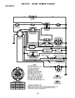
Check wiring.  See electrical wiring diagram in the Repair
Parts section.

TO REPLACE FUSE

Replace with 20 amp automotive-type plug-in fuse.  The fuse
holder is located behind the dash.

FIG. 29

ENGINE

TO ADJUST THROTTLE CONTROL CABLE
(See Fig. 30)

The throttle control has been preset at the factory and
adjustment should not be necessary. Check adjustment as
described below before loosening cable. If adjustment is
necessary, proceed as follows:

With engine not running, move throttle control lever from
slow to choke position. Slowly move lever from choke to
fast position.

Check that hole in throttle lever and hole in plate line up.
If holes “A” are not aligned, loosen clamp screw and
move throttle cable until  holes are aligned. Tighten
clamp screw securely.

FAST

 IDLE SPEED
SCREW

THROTTLE
LEVER

PLATE

THROTTLE CABLE

CLAMP
SCREW

 HOLE “A”

FIG. 30

TO ADJUST CARBURETOR

The carburetor has been preset at the factory and adjust-
ment should not be necessary. However, minor adjustment
may be required to compensate for differences in fuel,
temperature, altitude or load. If the carburetor does need
adjustment, see engine manual.

High speed stop is factory adjusted. Do not adjust - damage
may result.

IMPORTANT:

NEVER TAMPER WITH THE ENGINE

GOVERNOR, WHICH IS FACTORY SET FOR PROPER
ENGINE SPEED. OVERSPEEDING THE ENGINE ABOVE
T H E   F A C T O R Y   H I G H   S P E E D   S E T T I N G   C A N   B E
DANGEROUS. IF YOU THINK THE ENGINE-GOVERNED
HIGH SPEED NEEDS ADJUSTING, CONTACT YOUR
N E A R E S T   A U T H O R I Z E D   S E R V I C E   C E N T E R /
DEPARTMENT, WHICH HAS PROPER EQUIPMENT AND
E X P E R I E N C E   T O   M A K E   A N Y   N E C E S S A R Y
ADJUSTMENTS.

Summary of Contents for S165H42C

Page 1: ...AL MODEL NO S165H42C 16 5 HP 42 Inch LawnTractor For Parts and Service contact our authorized distributor call 1 800 849 1297 For Technical Assistance call 1 800 829 5886 178704 Rev 1 4 16 01 TR PRINT...

Page 2: ...acturer s recommendations for wheel weights or counterweights to improve stability Useextracarewithgrasscatchersorotherattachments These can change the stability of the machine Keep all movement on th...

Page 3: ...for Ride On Mowers SAFETY RULES SAFETY RULES 2 3 PRODUCT SPECIFICATIONS 4 CUSTOMER RESPONSIBILITIES 4 15 18 ASSEMBLY 6 8 OPERATION 9 14 MAINTENANCE SCHEDULE 15 SERVICE AND ADJUSTMENTS 19 23 STORAGE 2...

Page 4: ...s to service or repair this tractor Please read and retain this manual The instructions will enable you to assemble and maintain your tractor properly Always observe the SAFETY RULES CUSTOMER RESPONSI...

Page 5: ...sher 1 Locknut 5 16 18 1 Hex Bolt 5 16 18 x 1 1 4 1 Hex Bolt 3 8 16 x 1 1 Lockwasher 3 8 Steering Boot Steering Extension Shaft Steering Wheel Adapter 1 Bolt 1 Washer 17 32 x 1 3 16 x 12 Gauge Seat 2...

Page 6: ...securely IMPORTANT TIGHTEN BOLT AND NUT SECURELY TO 18 22 FT LBS TORQUE Place tabs of steering boot over tab slots in dash and push down to secure INSTALL STEERING WHEEL Position front wheels of the t...

Page 7: ...renginehasstarted movethrottle control to idle position Releaseparkingbrake Slowlymovethemotioncontrolleverforwardandslowly drive tractor off skid Applybraketostoptractor setparkingbrakeandplace motio...

Page 8: ...h fresh clean regular unleaded gasoline 3 Become familiar with all controls their location and function Operate them before you start the engine 3 Be sure brake system is in safe operating condition 3...

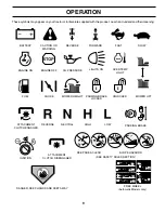
Page 9: ...RD FAST SLOW ENGINE ON ENGINE OFF OIL PRESSURE LIGHTS ON FUEL CHOKE MOWER HEIGHT PARKING BRAKE LOCKED UNLOCKED REVERSE NEUTRAL HIGH LOW ATTACHMENT CLUTCH ENGAGED MOWER LIFT DANGER KEEP HANDS AND FEET...

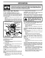
Page 10: ...TCH BRAKE PEDAL Used for declutching and brak ing the tractor and starting the engine PARKINGBRAKE Locksclutch brakepedalintothebrake position LIFT LEVER PLUNGER ATTACHMENT LIFT LEVER PARKING BRAKE IG...

Page 11: ...EDAL IS DEPRESSED ENGINE Move throttle control to slow position NOTE Failure to move throttle control to slow position and allowingenginetoidlebeforestoppingmaycauseengineto backfire Turn ignition key...

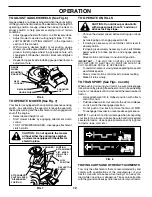
Page 12: ...slot and release so it is held in the disengaged position Do not push or tow tractor at more than two 2 MPH To reengage transmission reverse above procedure NOTE To protect hood from damage when trans...

Page 13: ...on dipstick is reached Do not overfill For cold weather operation you should change oil for easier starting See OIL VISCOSITY CHART in the Customer Responsibilities section of this manual To change e...

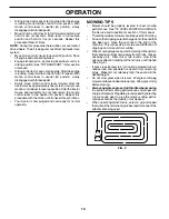
Page 14: ...ttachments select a ground speed thatwillsuittheterrainandgivebestperformanceofthe attachment being used OPERATION Sitting in the tractor seat start engine After the engine is running move throttle co...

Page 15: ...tery 7 Tighten front axle pivot bolt to 35 ft lbs maximum Do not overtighten 1 12 3 2 5 5 6 7 GENERAL RECOMMENDATIONS The warranty on this tractor does not cover items that have beensubjectedtooperato...

Page 16: ...nte nance BRAKE OPERATION If tractor requires more than six 6 feet stopping distance at high speed in highest gear then brake must be adjusted See TOADJUSTBRAKE intheServiceandAdjustments section of t...

Page 17: ...40 F C 32 10 10 60 5W 30 SAE 30 NOTE Although multi viscosity oils 5W30 10W30 etc improve starting in cold weather these multi viscosity oils will result in increased oil consumption when used above 3...

Page 18: ...romoverheating Hoodandengine blower housing must be removed to clean engine cooling fins Remove hood See TO REMOVE HOOD AND GRILL ASSEMBLY intheServiceandAdjustmentssectionof this manual Removescrewss...

Page 19: ...adjustment nut on that side TRACTOR TO REMOVE MOWER See Fig 16 Mower will be easier to remove from the right side of tractor Place attachment clutch in DISENGAGED position Move attachment lift lever f...

Page 20: ...actor Measuredistance D directly in front and behind the mandrel at bottom edge of mower housing as shown Before making any necessary adjustments check that both front links are equal in length Both l...

Page 21: ...r deck height to the lowest position After above adjustment is made if the tractor still creeps forward or backward while motion control lever is in neutral position follow these steps Loosen the adju...

Page 22: ...snap retaining ring securely in axle groove Replace axle cover NOTE To seal tire punctures and prevent flat tires due to slow leaks tire sealant may be purchased from your local parts dealer Tire seal...

Page 23: ...eck adjustment as described below before loosening cable If adjustment is necessary proceed as follows Withenginenotrunning movethrottlecontrolleverfrom slowtochokeposition Slowlymoveleverfromchoketo...

Page 24: ...G IN ESSENTIAL FUEL SYSTEM PARTS SUCH AS CARBURETOR FUEL FILTER FUEL HOSE OR TANK DURING STORAGE ALSO EXPERIENCE INDICATES THAT ALCOHOL BLENDED FUELS CALLED GASOHOL OR USING ETHANOL OR METHANOL CAN AT...

Page 25: ...ty ignition switch 7 Check replace ignition switch 8 Faulty solenoid or starter 8 Check replace solenoid or starter 9 Faulty operator presence switch es 9 Contact an authorized service center departme...

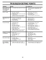
Page 26: ...Mower deck not level 4 Level mower deck 5 Low uneven tire air pressure 5 Check tires for proper air pressure 6 Worn bent or loose blade 6 Replace sharpen blade Tighten blade bolt 7 Buildup of grass le...

Page 27: ...R TRACTOR IS EQUIPPED WITH A SPECIAL ALTERNATOR SYSTEM THE LIGHTS ARE NOT CONNECTED TO THE BATTERY BUT HAVE THEIR OWN ELECTRICAL SOURCE BECAUSE OF THIS THE BRIGHTNESS OF THE LIGHTS WILL CHANGE WITH EN...

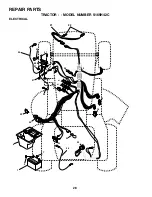
Page 28: ...28 28 29 26 24 42 43 27 27 25 41 27 27 40 33 30 8 2 1 27 16 16 52 D C AM PE RE S 45 22 21 REPAIR PARTS TRACTOR MODEL NUMBER S165H42C ELECTRICAL 81 81 81...

Page 29: ...6 red 25 146147 Cable Battery 6 Ga w 16 wire red 26 175158 Fuse 27 73510400 Nut Keps Hex 1 4 20 unc 28 4207J Cable Ground 6 Ga 12 black 29 121305X Switch Plunger Nc Gray 30 175566 Switch Ign 33 140401...

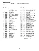
Page 30: ...ODEL NUMBER S165H42C CHASSIS AND ENCLOSURES 37 37 3 2 35 3 26 3 35 26 33 10 34 1 208 11 17 29 28 208 13 207 20 207 23 12 51 57 53 52 54 55 24 26 25 26 25 3 31 24 30 209 8 209 6 16 9 15 209 209 5 5 145...

Page 31: ...Lock Hex w Insert 3 8 16 UNC 28 150407 Grill Lens Asm 29 150209X599 LensQuadra 30 169467X550 Fender Asm 31 136619 BracketFender 33 105476X550 Footrest Lh 34 105475X550 Footrest Rh 35 72110606 Bolt RdH...

Page 32: ...64 65 212 63 116 70 57 66 27 51 48 151 202 49 47 50 120 150 156 166 165 82 168 163 14 164 21 8 10 83 159 161 198 158 162 171 169 29 28 32 30 52 32 53 35 55 36 62 35 36 22 34 61 16 1 77 77 30 61 52 96...

Page 33: ...ew 3 8 16 x 3 4 62 8883R Cover Pedal 63 175410 Pulley Engine 64 71170764 Bolt Hex 7 16 x 4 Gr 5 65 10040700 Washer 66 154778 Keeper Belt Engine Hydro 69 142432 Screw Hex Wsh Hi Lo 1 4 1 2 Unc 70 13468...

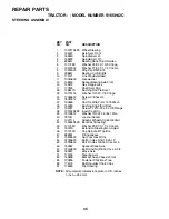
Page 34: ...TOR MODEL NUMBER S165H42C STEERING ASSEMBLY 44 51 54 5 9 5 7 7 9 4 3 32 43 6 43 8 10 40 11 8 6 9 46 46 8 6 9 2 47 47 26 30 28 1 41 42 37 36 37 38 63 11 39 68 67 67 67 13 65 85 85 68 15 15 15 29 29 82...

Page 35: ...36 155099 Bushing Strg 5 8 Id Dash 37 152927 Screw TT 10 32 x 5 x 3 8 Flange 38 133742X428 Insert Cap Strg 39 19133812 Washer 13 32 x 2 3 8 x 12Ga 40 7810H LocknutCenter 41 100711L Adaptor Wheel Strg...

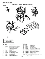
Page 36: ...ank Fuel 2 00 Fr 32 161493 Cap Asm Fuel w Gauge REPAIR PARTS TRACTOR MODEL NUMBER S165H42C ENGINE 2 1 OPTIONAL EQUIPMENT Spark Arrester 29 62 13 4 85 78 78 81 3 16 44 46 32 31 33 37 33 23 45 14 38 40...

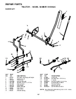
Page 37: ...KEY PART NO NO DESCRIPTION NOTE All component dimensions given in U S inches 1 inch 25 4 mm REPAIR PARTS TRACTOR MODEL NUMBER S165H42C MOWER LIFT 15 20 16 1718 20 20 15 20 4 5 6 2 3 1 6 5 4 7 8 12 11...

Page 38: ...Washer 17 32 x 1 3 16 x 12 Ga 25 127018X Bolt Shoulder 5 16 18 x 62 26 10040800 Lockwasher 26 23 1 24 16 15 12 13 17 25 4 3 8 9 7 8 9 7 2 6 22 21 5 10 5 14 1 140116 Seat 2 140551 Bracket Pnt Pivot Sea...

Page 39: ...All component dimensions given in U S inches 1 inch 25 4 mm KEY PART NO NO DESCRIPTION KEY PART NO NO DESCRIPTION 10 157002 DecalDangerEnglish 11 4900J Decal Clutch brake English 12 177430 DecalFende...

Page 40: ...3 146 148 145 150 45 144 147 147 142 149 142 49 50 51 54 52 53 55 56 34 1 46 44 21 22 24 25 26 27 2 28 29 23 21 21 21 18 18 20 2 48 59 19 4 3 5 6 21 40 143 36 40 37 40 159 152 151 153 154 157 158 67 1...

Page 41: ...2 139888 Bolt Shoulder 5 16 18 UNC 53 131845 Arm Assembly Pad Brake 54 133943 Washer Hardened 55 155046 Arm Idler 56 165723 Spacer Retainer 59 141043 Guard TUV Idler 67 106932X Knob 68 144959 V Belt 4...

Page 42: ...limited to 90 days from the date of original purchase 5 This Warranty applies only to products which have been properly assembled adjusted operated and main tained in accordance with the instructions...

Page 43: ...IGHTING GUIDE ONLY RIDE UP AND DOWN HILL NOT ACROSS HILL SUGGESTED GUIDE FOR SIGHTING SLOPES FOR SAFE OPERATION Operate your Tractor up and down the face of slopes not greater than 15 never across the...

Page 44: ......
Reviews: