


www.weedrazers.com
3
Notes:
Assembly & Instructions
Tools Required:
• #3 Phillips Screwdriver
• 7/16” Wrench
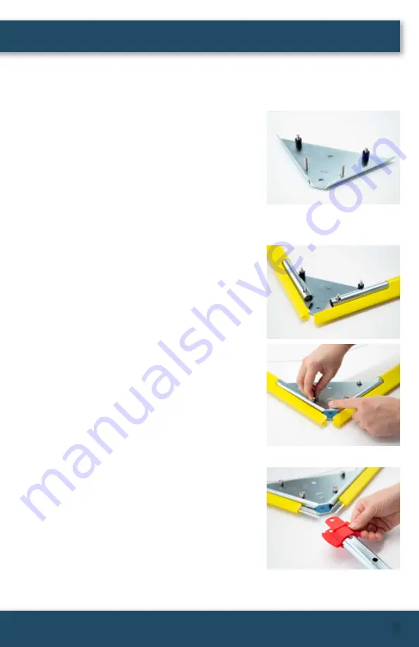
Step 1
Insert 4 of the 1.2” Bolts (J) into the four outermost
holes of one of the triangular Support Brackets (D)
making sure to slide the bolts through the domed
side, then place the bracket on a flat work surface
with the screw heads down. Place a Nylon Spacer
(G) on each of the bolts at the base of the triangular
bracket.
Step 2
Place each Blade (C) onto the Support Bracket (D)
so that each blade edge faces outward and the
holes seat over the two bolts at the narrow end
of the triangular bracket. Next, seat the second
triangular Support Bracket (D) over the assembly
with the domed side facing up and place a washer
and nut on each of the four bolts—be sure to
simply hand tighten at this time.
Step 3
Slide the blade covers back about 2” to make
room for the handle. Take the two halves of the
Weed Deflector (F) and snap together at the pins
molded into each piece. Slip the Weed Deflector
(F) onto the Angled Handle (B) at the end with
two holes making sure that the hole in the Weed
Deflector aligns with the second hole from the end,
then slide the Angle Handle (B) into the Support
Bracket (D) so that the holes align. At this time, the
blade covers can be slid back into place for safety
and will ride up over the Weed Deflector slightly.


