
Chapter 5
17
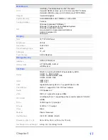
Main Board
CPU
Intel® Bay Trail-Mobile/Desktop SoC Processor:
Celeron® N2930 (4 cores, up to 2.16 GHz, max TDP 7.5 Watt)
Celeron® J1900 (4 cores, up to 2.42 GHz, max TDP 10 Watt)
Graphic
Intel® HD Graphics
System Memory
SO-DIMM DDR3L 1067/1333MHz x 1, Max. 8GB
Cooing Solution
Fan-less
OS
Windows Embedded POSReady 7
Windows 7 Professional for Embedded Systems
Windows Embedded 8 Industry
Linux kernel 3.0+ & associated distributions
Android Compliant OS
Window 10
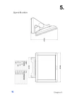
Display
Size
15" TFT LCD Panel
Brightness
250 nit
Resolution
1024 X 768
Panel backlight type
LED
Tilt Angle
17
°
~67
°
Touch Screen
5 Wire Resistive
Storage Device
Interface
SATAII (3.0Gb/S) x 2
HDD or SSD
2.5" SATA HDD / SSD x 1
mSATA slot x 1
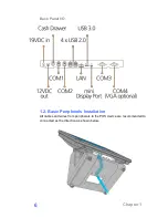
I/O Ports
Serial
RS-232 x 4, pin9 with RI/5V/12V selectable by BIOS
COM 1 / 2 : RS232, RJ50
COM 3 : RS232/422/485, DB9
COM 4 : RS232, DB9
USB
USB 2.0 x 4
USB 3.0 x 1
LAN
Gigabit Ethernet by RJ-45 x 1, support Wake on LAN
Cash Drawer
RJ12 x 1, support 12V / 24V DC cash drawer
Audio
2 W Speaker x 2
VGA
DB15 x 1 optional for replace COM4
DP / HDMI
mini Display Port x 1 (supporting active converter cable to VGA,DVI,
HDMI)
DC-in
19VDC input x 1, 2pins jack
DC-out
12VDC x 1 / 1A output
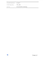
Color
Black
Material
Plastic / Aluminum
Certifications
CE / FCC / WEEE / RoHS
Dimension (W x D x H)
36.5 x 22.9 x 33.2 cm (14.4 x 9 x 13 inch)
Net Weight / Gross Weight
6.8 kg, 15.1 lb / 8.8 kg, 19.6 lb


