134
CHAPTER 6 - DETAILED PARAMETER DESCRIPTION
Range
[Factory Setting]
Parameter
Unit
Description / Notes
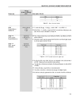
739 to 800 (P296 = 4)
[ 800 ]
1 V
809 to 1000 (P296 = 5)
[ 1000 ]
1 V
885 to 1000 (P296 = 6)
[ 1000 ]
1 V
924 to 1000 (P296 = 7)
[ 1000 ]
1 V
1063 to 1200 (P296 = 8)
[ 1200 ]
1 V
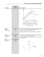
E01 - Overvoltage Level
Regulation Level
Time
Time
Speed
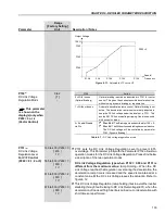
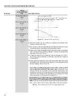
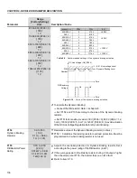
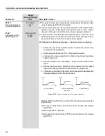
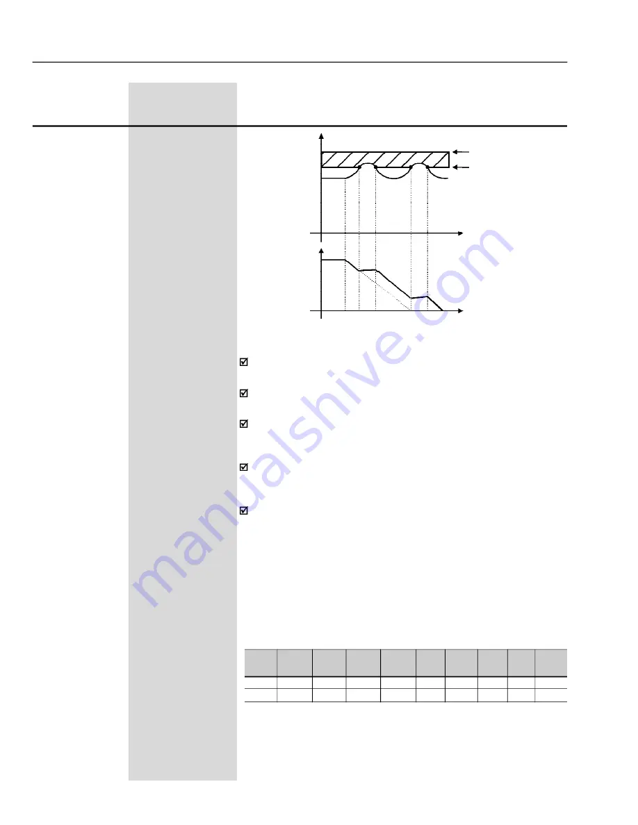
Figure 6.12 -
Deceleration with ramp holding
P151
Nominal
DC Link Voltage (Ud) (P004)
With this function you can achieve an optimized deceleration time
(minimum) for the driven load.
This function is useful in application where loads with medium moment
of inertia are driven, that require short deceleration ramps.
If even so the inverter is disabled during the acceleration due to overvoltage
(E01), reduce the value of P151 gradually, or increase the deceleration
ramp time (P101 and/or P103).
In case the supply line is permanently under overvoltage (Ud > P151),
the inverter cannot decelerate. In this case reduce the line voltage or
increment P151.
If even after these settings the motor cannot decelerate within the required
deceleration time, use the dynamic braking. (For more details about the
dynamic braking, refer to item 8.10).
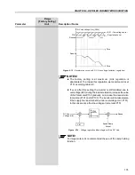
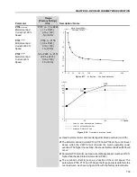
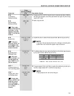
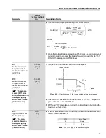
Type of DC Link Voltage Regulation when P152 > 0.00 and P151
are set different that than the maximum value:
When the DC Link
Voltage reaches the regulation level during the deceleration, the
deceleration ramp time is increased and the motor is also accelerated
until the DC Link voltage leaves the defined over-voltage level. There
after deceleration is continued. Refer to figure 6.13.
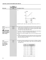
Inverter
V
rated
P296
P151
220/
230 V
0
375 V
380 V
1
618 V
400/
415 V
2
675 V
440/
460 V
3
748 V
480 V
4
780 V
500/
525 V
5
893 V
550/
575 V
6
972 V
600 V
7
972 V
660/
690 V
8
1174 V
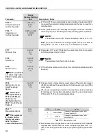
Table 6.8 -
Recommended values for DC Link voltage regulation level

