137
CHAPTER 6 - DETAILED PARAMETER DESCRIPTION
Range
[Factory Setting]
Parameter
Unit
Description / Notes
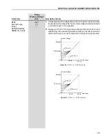
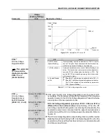
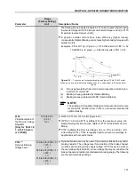
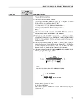
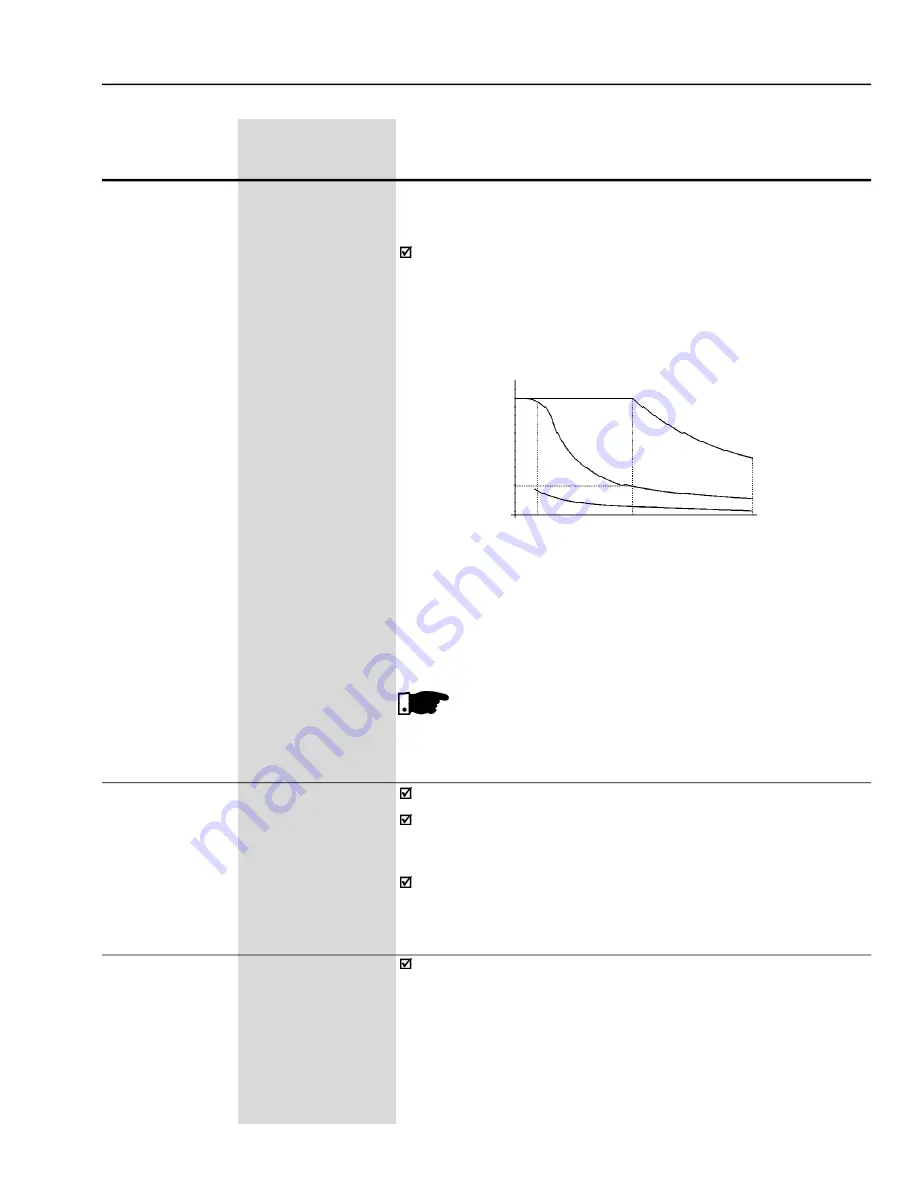
(a)
Torque generated by the motor in normal operation, driven by an
inverter in “motor mode”.
(b)
Braking torque generated by Optimal Braking
(c)
Braking torque generated with DC Injection Braking
NOTE!
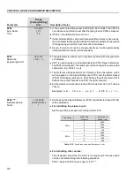
The enabling of the optimal braking can increase the motor noise
level and the vibration level. If this is not desired, disable the
optimal braking.
Torque (PU)
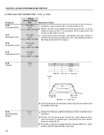
Figure 6.15
- T x rpm curve for optimal braking and typical 10 hp/7.5 kW motor
driven by an inverter with torque limitation set for a value equal to the rated motor
torque
1.0
TB1
0
(a)
(b)
(c)
Speed (PU)
0
0.2
1.0
2.0
P152
0.00 to 9.99
Proportional Gain of
[ 0.00 ]
the DC Link Voltage
0.01
Regulator
[Only for P202 = 0,
1, 2 (V/F Control)
or 5 (VVW)]
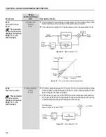
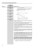
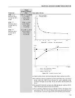
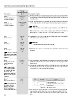
Refer to P151 for V/F Control (figure 6.14).
If P152 = 0.00 and P151 is different from the maximum value, the
Ramp Holding function is active. (Refer to P151 for the Scalar Control
Mode)
P152 multiplies the DC Link voltage error, i.e. DC Link actual - DC
Link setting (P151). P152 is typically used to prevent overvoltage in
applications with eccentric loads.
P153
(6)
339 to 400 (P296 = 0)
Dynamic Braking
[ 375 ]
Voltage Level
1 V
585 to 800 (P296 = 1)
[ 618 ]
1 V
616 to 800 (P296 = 2)
[ 675 ]
1 V
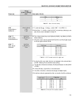
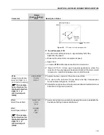
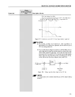
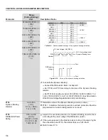
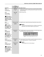
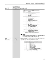
Dynamic braking can only be used if the inverter is fitted with a dynamic
braking resistor. The voltage level for actuation of the brake chopper
must be set according to the supply voltage. If P153 is set too close to
the overvoltage trip level (E01) an overvoltage trip may occur before the
brake chopper and resistor can dissipate the braking energy. The following
are the recommended settings:
The braking torque indicated in figure 6.15 can be increased by increasing
the inverter torque limit: P169 (maximum forward torque current) or P170
(maximum reverse torque current).
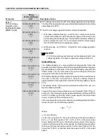
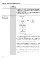
In general, smaller motors have lower efficiency (higher losses)
consequently Optimal Braking can achieve higher braking torques with
smaller motors.
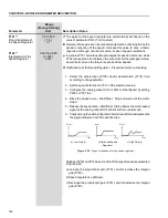
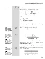
Examples: 0.75 kW/1 hp, IV poles:
= 0.76 that results in TB1 = 0.32
15 kW/20 hp, IV poles:
= 0.86 that results in TB1 = 0.16


