177
CHAPTER 6 - DETAILED PARAMETER DESCRIPTION
DI1
24 V
Motor Speed
Decel. Ramp
DIx
Open
Time
Motor Speed
Motor Coasts to Stop
Time
Time
Time
24 V
Accel. Ramp
Accel. Ramp
Open
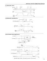
a) START/STOP
b) GENERAL ENABLE
Note:
All digital inputs set to general enable must be on in
order that the inverter operates as shown above.
Note:
All digital inputs set to start/stop must be on in order
that the inverter operates as shown above.
Open
24 V
Time
Time
Motor Speed
DIx
Open
24 V
Time
Time
Motor Speed
DIx
FWD
REV
d) FWD/REV
c) NO EXTERNAL FAULT
Motor Coasts to Stop
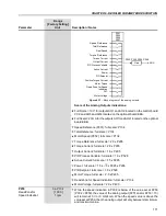
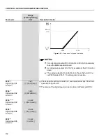
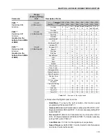
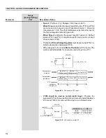
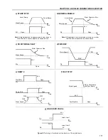
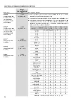
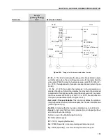
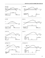
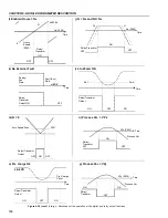
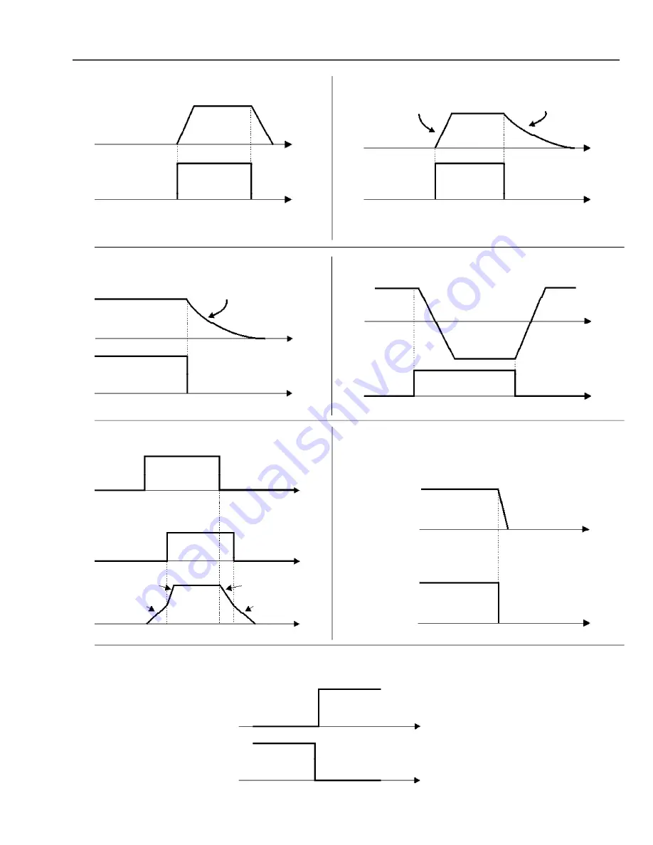
Figure 6.37 a) to g)
- Details about the function of the digital inputs
Open
Open
24 V
Time
Time
24 V
Time
P102
P100
Start/Stop
DIx
Ramp 2 DIx
e) RAMP 2
Open
Time
Time
Motor Speed
24 V
Fast Stop DIx
Motor Decelerates
with Zero Ramp
Motor Speed
f) FAST STOP
P103
P101
g) LOAD USER VIA DIx
Time
Time
Load User 1
Load User 2
DIx
24 V
24 V
DIx
0 V
0 V

