295
CHAPTER 8 - CFW-09 OPTIONS AND ACCESSORIES
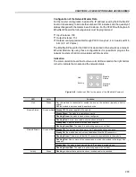
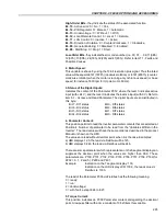
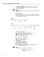
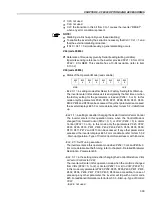
High-Order Bits
- they indicate the status of the associated function
EL.15
- Active error: 0 = No, 1 = Yes;
EL.14
- PID Regulator 0 = Manual, 1 = Automatic;
EL.13
- Undervoltage : 0 = Without, 1 = With;
EL.12
- Local/Remote Control: 0 = Local, 1 = Remote;
EL.11
- JOG Control: 0 = Inactive, 1 = Active;
EL.10
- Direction of rotation: 0 = Counter-Clockwise, 1 = Clockwise;
EL.09
- General Enabling: 0 = Disabled, 1 = Enabled;
EL.08
- Start/Stop: 0 = Stop, 1 = Start.
Low-Order Bits
- they indicate the error code number, (i.e. 00, 01, ... ,09, 11(0Bh),
12(0Ch), 13(0Dh), 24(18h), 32(20h) and 41(29h) ). Refer to item 7.1- Faults and
Possible Causes.
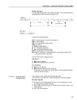
2. Motor Speed:
This variable is shown by using the 13-bit resolution plus signal. Thus the rated
value will be equal to 8191(1FFFh) (clockwise rotation) or -8191(E001h) (counter-
clock wise rotation) when the motor is running at synchronous speed (or base
speed, for instance 1800 rpm for IV-pole motor, 60 Hz).
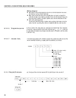
3. Status of the Digital Inputs:
Indicates the content of the Parameter P012, where the level 1 indicates active
input (with +24 V), and the level 0 indicates the inactive input (with 0 V). Refer to
item 6.1 - Access and Read Parameter. The digital inputs are so distributed in
this byte:
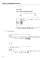
Bit.7 - DI1 status
Bit.3 - DI5 status
Bit.6 - DI2 status
Bit.2 - DI6 status
Bit.5 - DI3 status
Bit.1 - DI7 status
Bit.4 - DI4 status
Bit.0 - DI8 status
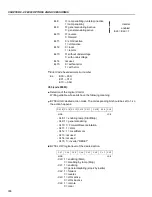
4. Parameter Content:
This position permits to read the inverter parameter contents that are selected at
Position 4. Number of parameter to be read from the “Variables Written in the
Inverter”. The read values will have the same order as described in the product
Manual or shown on the HMI.
The values are read without decimal point, when it is the case. Examples:
a) HMI displays 12.3, the read via Fieldbus will be 123,
b) HMI displays 0.246, the read via Fieldbus will be 246.
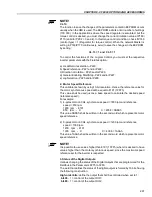
There are some parameters which representation on the 5 segment display can
suppress the decimal point when the values are higher than 99.9. These
parameters are: P100, P101, P102, P103, P155, P156, P157, P158, P169 (for
P202 = 0, 1, 2 and 5), P290 and P401.
Example:
Indication on the 7 segment display: 130,
Indication on the LCD display LCD: 130.0, the read value via
Fieldbus is: 1300.
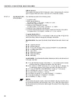
The read of the Parameter P006 via Fieldbus has the following meaning:
0 = ready;
1 = run;
2 = Undervoltage;
3 = with fault, except E24 to E27.
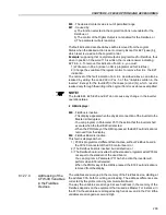
5. Torque Current:
This position indicates de P009 Parameter content, disregarding the decimal
point. A lowpass filter with a time constant of 0.5s filters this variable.

