296
CHAPTER 8 - CFW-09 OPTIONS AND ACCESSORIES
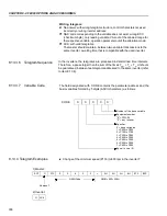
6. Motor Current:
This position indicates de P003 Parameter content, disregarding the decimal
point. A lowpass filter with a time constant of 0.3 s filters this variable.
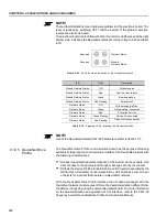
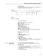
The variables are written in the following order:
1 - Logical Control;
2 - Motor speed reference,
for option P309 = 1 or 4 (2I/O) - it writes in 1 and 2;
3 - Status of the Digital Outputs;
4 - Number of the Parameter to be read,
for option P309 = 2 or 5 (4I/O) - it writes in 1, 2, 3 and 4;
5 - Number of the Parameter to be changed;
6 - Content of the Parameter to be changed, selected in the previous position,
for option P309 = 3 or 6 (6I/O) - it writes in 1, 2, 3, 4, 5 and 6.
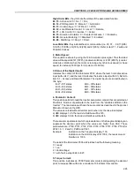
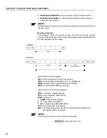
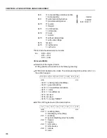
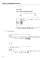
1. Logical Control (C.L.):
The word that defines the C.L. is formed by 16 bits, being 8 bits of high orders
and 8 bits of low orders and having the following construction:
High-Order Bits
- they select the function that shall be driven when the bit is set
to 1.
CL.15
- Inverter fault reset;
CL.14
- Without function;
CL.13
- To save the changes of the parameter P169/P170 in the EEPROM;
CL.12
- Local/Remote control;
CL.11
- Jog control;
CL.10
- Direction of rotation;
CL.09
- General enabling;
CL.08
- Start/Stop.
Low-Order Bits
- they determine the status that is wanted for the function selected
in the high-order bits.
CL.7
- Inverter fault reset: always it varies from 0
1, an inverter reset is caused,
with the presence of faults (except E24, E25, E26 e E27);
CL.6
- No function / STOP detection. It is not necessary to activate the
correspondent upper bit (refer to the description of parameter P310);
CL.5
- To save P169/P170 in the EEPROM: 0 = to save, 1 = to not save;
CL.4
- Local/Remote control: 0 = Local, 1 = Remote;
CL.3
- Jog control: 0 = Inactive, 1 = Active;
CL.2
- Direction of rotation: 0 = counter-clockwise, 1 = clockwise;
CL.1
- General enabling: 0 = Disabled, 1 = Enabled;
CL.0
- Start/Stop: 0 = Stop, 1 = Start.
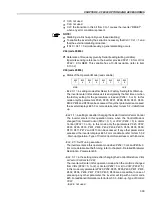
NOTE!
The inverter will execute only the command indicated in the low-order bit, when
the corresponding high-order bit has the value 1 (one). When the high-order bit
has the value 0 (zero), the inverter will disregard the value of the corresponding
low-order bit.
8.12.7.2
Variables Written
in the Inverter

