320
CHAPTER 8 - CFW-09 OPTIONS AND ACCESSORIES
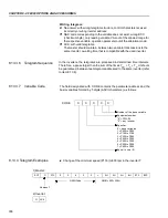
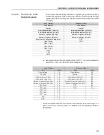
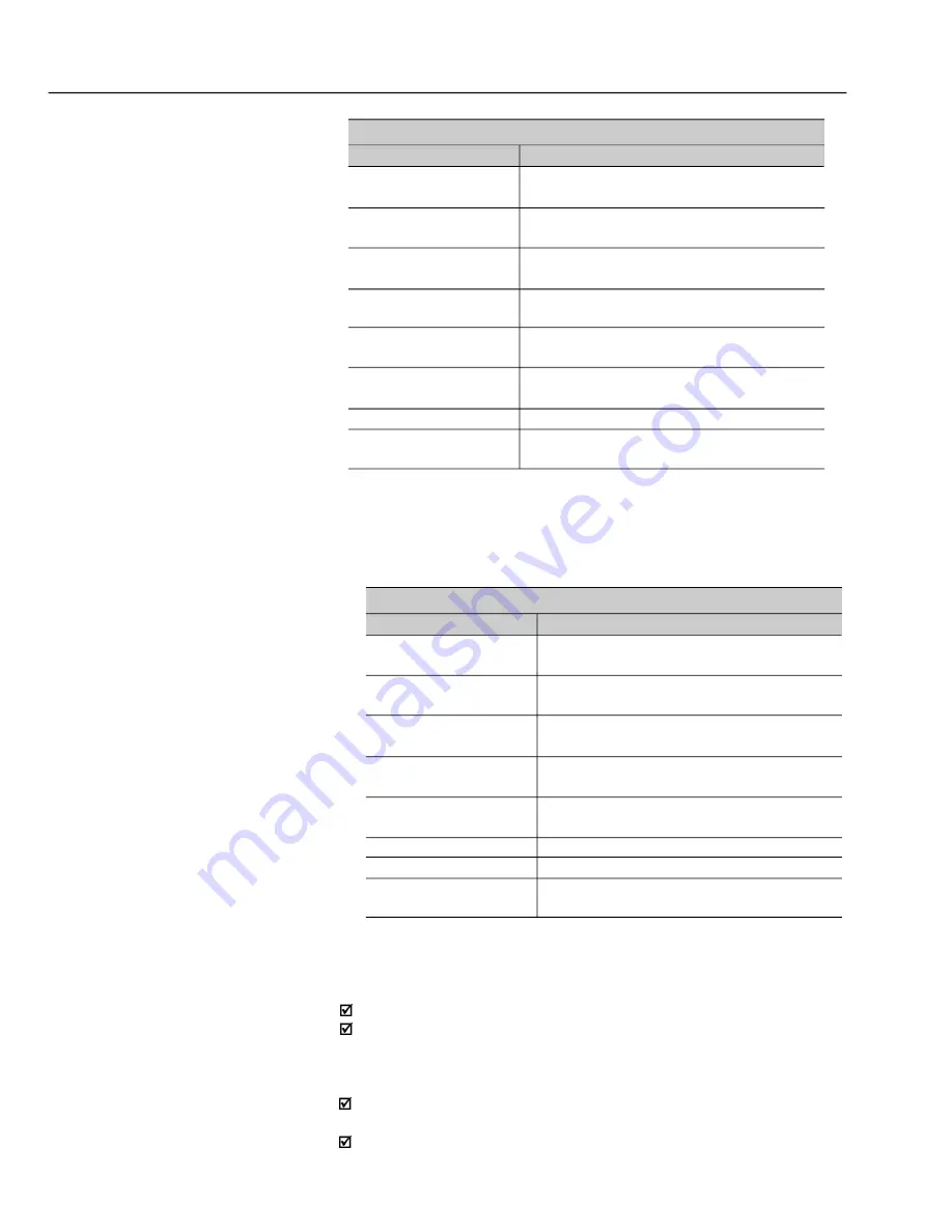
The command bits are available to read and write and they have the same
function of the logic command bits 0 to 7 (basic variable 3), however no requiring
the use of the mask. The basic variable 3 write influences the status of these
bits.
Bit Number
Bit 100
Bit 101
Bit 102
Bit 103
Bit 104
Bit 105
Bit 106
Bit 107
Command Bits
Function
0 = Ramp disable (Stop)
1 = Ramp enable (Start)
0 = General disable
1 = General enable
0 = Counter-clockwise direction of rotation
1 = Clockwise direction of rotation
0 = JOG disable
1 = JOG enable
0 = Goes to local mode
1 = Goes to remote mode
Not used
Not used
0 = It does not reset inverter
1 = It resets inverter
8.14.3
Detailed Function
Description
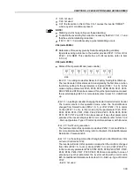
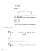
This Item describes in details the functions that are available in the CFW-09
for the Modbus RTU communication. Please note the following during the
message preparation:
Values are always transmitted as hexadecimal values.
The address of one data, the data number and the value of the registers
are always represented through 16 bits. Thus these fields are transmitted
by using two bytes (high and low). To access the bits, and the form to
represent one bit depend on the used function.
The messages, both for enquiry and response, cannot be longer than 128
bytes.
The resolution of each parameter or basic variable is as described in item
8.13.3.2.
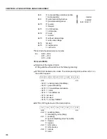
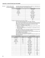
Bit Number
Bit 0
Bit 1
Bit 2
Bit 3
Bit 4
Bit 5
Bit 6
Bit 7
Status Bits
Function
0 = Ramp enabling inactive
1 = Ramp enabling active
0 = General enabling inactive
1 = General enabling active
0 = Counter-clockwise direction of rotation
1 = Clockwise direction of rotation
0 = JOG inactive
1 = JOG active
0 = Local Mode
1 = Remote Mode
0 = No undervoltage
1 = With undervoltage
Not used
0 = No fault
1 = With fault

