57
CHAPTER 3 - INSTALLATION AND CONNECTION
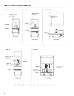
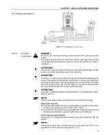
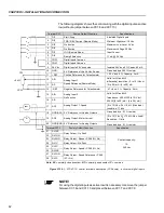
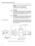
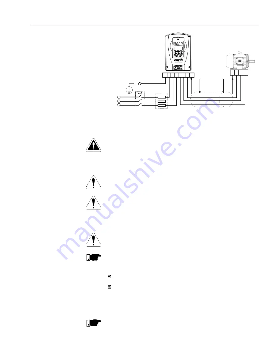
Figure 3.9
- Power/grounding connections
Fuses
Power
Supply
Shielding
PE
Disconnect
R
S
T
PE
R S T U V W PE
PE W V U
3.2.5 Power Connections
DANGER!
Provide an AC input disconnecting switch to switch OFF input power to the
inverter.
This device shall disconnect the inverter from the AC input supply when required
(e.g. during maintenance services). However it cannot be used as an emergency
stop device.
ATTENTION!
The neutral conductor of the AC input for the inverter must be physically grounded,
but do not use it for grounding purpose of the inverter(s).
ATTENTION!
A contactor or another device that frequently disconnects and reapplies the AC
supply to the inverter in order to start and stop the motor may cause damage to
the inverter power section. The drive is designed to use control signals for starting
and stopping the motor. If used, the input device must not exceed one operation
every 6 minutes otherwise the inverter may be damaged.
ATTENTION!
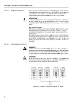
Set jumper to select the rated line voltage 380-480 V, for inverters 86 A or higher.
Refer to item 3.2.3.
NOTE!
The AC input voltage must be compatible with the inverter rated voltage.
Supply line capacity
:
The CFW-09 is suitable for use in circuits capable of supplying not more than
30.000 A (rms) symmetrical (230 V/480 V/600 V/690 V).
The CFW-09 can be installed on power supplies with a higher fault level provided
that adequate protection is provided by the fuses or circuit breaker.
DC Link Inductor/Line Reactor
Refer to item 8.7 relating to the requirement for using the Line Reactor / DC Link
Inductor.
NOTE!
Capacitors for power factor correction are not required at the input (R, S,T) and
they MUST not be connected at the output (U, V, W).
3.2.5.1
AC Input
Connection

